Last week I was invited by Isotropix to talk about the work that I'm doing with Clarisse, as part of the Siggraph London events. This was my little talk.
Paddington for M&S /

After a few years working exclusively on feature films, this 2017 I had the opportunity to work on two different projects. I can't talk about the first one yet, but the second one where I spent around 3 months, is a commercial for Mark&Spencer based on Paddington Bear.
Everything was executed at Framestore London.
Mixing displacement and multiple bump maps /
A very common situation when look-deving an asset is combining various displacement and bump maps. Having them in different texture maps gives you the possibility to play with them and making very fast changes without going back to Mari and Zbrush and waste a lot of time going back and forward until reaching the right look. You also want to keep busy your look-dev team, of course.
While ago I told you how to combine different displacement maps coming from different sources, today I want to show you how to combine multiple bump maps, with different scales and values. This is a very common situation in vfx, I would say every single asset has at least one displacement layer and one bump layer, but usually, you would have more than one. This is how you can combine multiple bump layers in Maya/Arnold.
- The first thing I'm going to do is add a displacement layer. To make this post easy I'm using a single displacement layer. Refer back to the tutorial I mentioned previously on this post to mix more than one displacement layer.
- Now connect your first bump map layer as usual. Connecting the red channel to the bump input of the shader.
- in the hypershade create a file texture for your second bump layer. In this case a low frequency noise.
- Create an avergage node and two multiply nodes.
- Connect the red channel of the first bump layer to the input 1 of the multiply node. Control the intensity of this layer with the input 2 of the multiply node.
- Repeat with previous step with the second bump layer.
- Connect the outputs of both multiply nodes to the inputs 3D0 and 3D1 of the average node.
- It is extremely important to leave the bump depth at 1 in order to make this work.
Cryptomatte in Fusion /
I'm using Fusion at home and trying to find workarounds for my texturing, look-dev and lighting pipeline. A must thing to have these days is cryptomatte, I can't see any work done without it, going back to ID passes is not an option.
- To install it properly, you need to place the 3 .lua files in the same directory where your Fusion executable is located.
- The fuse file should be places inside of your fuses folder and then blackmagic folder.
- Apparently at the time of writing this, there is a bug with cryptomatte for Fusion not reading properly the cryptomatte data inside of a multi channel .exr
- Rendering the cryptomate data in individual .exr is the best way to work.
- Having the cryptomatte in it's own .exr will save the pain of shuffle channels in Fusion.
- Use the add button and the color picker in the viewport to isolate parts of your render in the alpha channel.
Iron Patriot finished /
Let's say it is finished for now. It will be the asset used in my next texturing and look-dev course.
Iron Patriot wip 02 /
Another wip of this character. More to come.
Lighting spheres "tiny" /
Iron Patriot wip 01 /
I'm working on a texturing and look-dev course for elephant vfx and this is the asset that I'm preparing. Just an arm for now but I guess it's time to show you guys something. Stay tuned.
Split EXR in Fusion /
I recently started to use Blackmagic's Fusion at home (budget reasons) and I'm liking it so far but, one of the most important features coming from Nuke, is obviously the ability to shuffle between all the AOVs of your multi channel EXRs. Unfortunately Fusion doesn't support this. It has something called booleans to separate RGB channels but not AOVs.
Chad Ashley pointed me to this third party script that splits a multi channel EXR in many different loaders with each one of your AOVs. Not as good as Nuke's shuffle but good enough!
On-set tips: Creating high frequency detail /
In a previous post I mentioned the importance of having high frequency details whilst scanning assets on-set. Sometimes if we don't have that detail we can just create it. Actually sometimes this is the only way to capture volumes and surfaces efficiently, specially if the asset doesn't have any surface detail, like white objects for example.
If we are dealing with assets that are being used on set but won't appear in the final edit, it is probably that those assets are not painted at all. There is no need to spend resources on it, right? But we might need to scan those assets to create a virtual asset that will be ultimately used on screen.
As mentioned before, if we don't have enough surface detail it will be so difficult to scan assets using photogrammetry so, we need to create high frequency detail on our own way.
Let's say we need to create a virtual assets of this physical mask. It is completely plain, white, we don't see much detail on its surface. We can create high frequency detail just painting some dots, or placing small stickers across the surface.
In this particular case I'm using a regular DSLR + multi zoom lens. A tripod, a support for the mask and some washable paint. I prefer to use small round stickers because they create less artifacts in the scan, but I run out of them.
I created this support while ago to scan fruits and other organic assets.
The first thing I usually do (if the object is white) is covering the whole object with neutral gray paint. It is way more easy to balance the exposure photographing again gray than white.
Once the gray paint is dry I just paint small dots or place the round stickers to create high frequency detail. The smallest the better.
Once the material has been processed you should get a pretty decent scan. Probably an impossible task without creating all the high frequency detail first.
Hard light / soft light / specular light / diffuse light /
These days we are lucky enough to apply the same photographic and cinematographic principles to our work as visual effects artists lighting shots. That's why we are always talking about cinematography and cinematic language. Today we are going to talk about some very common techniques in the cinematography world: hard light, soft light, specular light and diffuse light.
The main difference between hard light and soft light do not eradicate in the light itself but in the shadows. When the shadow is perfectly defined and opaque we talk about hard light. When the shadows are diffuse we called it soft lighting, the shadows will also be less opaque.
Is there any specific lighting source that creates hard or soft lighting? The answer is no. Any light can create hard or soft lighting depending on two factors.
- Size: Not only the size of the practical lighting source but also the size in relationship with the subject that is being illuminated.
- Distance: In relation to the subject and the placement of the lighting source.
Diffraction refers to various phenomena that occur when a wave encounters an obstacle or a slit. It is defined as the bending of light around the corners of an obstacle or aperture into the region of geometrical shadow of the obstacle.

When a light beam impacts on the surface of an object, if the size of the lighting source is similar to the size of the object, the light beam will go parallel and get slightly curved towards the interior.

If the size of the lighting source is smaller than the object or it is placed far away from it, the light beam won't bend creating very hard and defined shadows.

If the lighting source is bigger than the subject and it's placed near of it, the light beam will get curved a lot generating soft shadows.

If the lighting source is way bigger than the subject and it's place near of it, the light beam will be curved a lot, even they will get mixed at some point. Consequently the profile of the subject will not be represented in the shadows.

If a big lighting source is placed very far of the subject, its size will be altered in relation with the subject, and its behavior will be the same as a small lighting source, generating hard shadows. The most common example of this is the sun. It is very far but still generates hard lighting. Only on cloudy days the sun lights gets diffused by the clouds.
In two lines
- Soft light: Big lighting sources and or close to the subject.
- Hard light: Small lighting sources and or far from the subject.
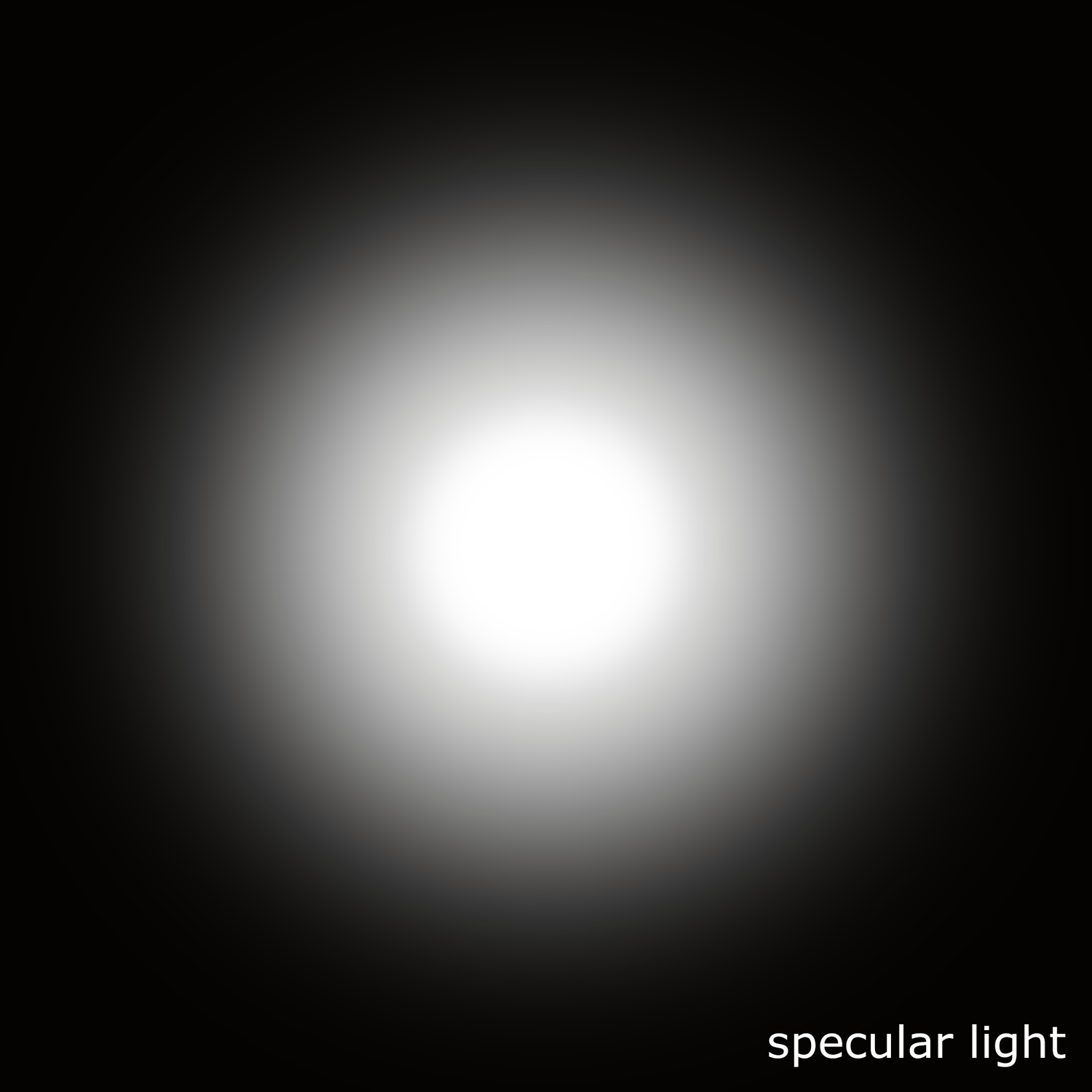
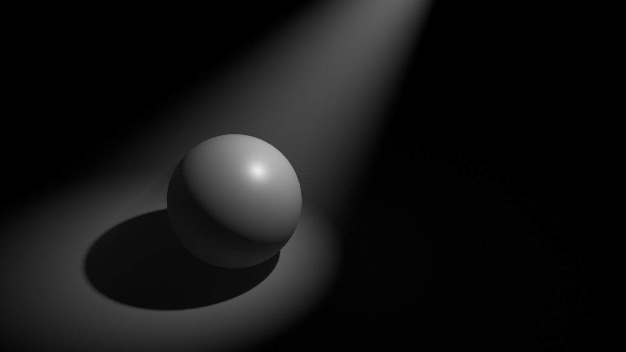
Specular light: Lighting source very powerful in the center that gradually loses energy toward its extremes. Like a traditional torch. It generates very exposed and bright areas in the subject. Like the lights used in photo calls and interviews.
Diffuse light: Lighting source with uniform energy all over its surface. The lighting tends to be more compensated when it hits the subject surface.
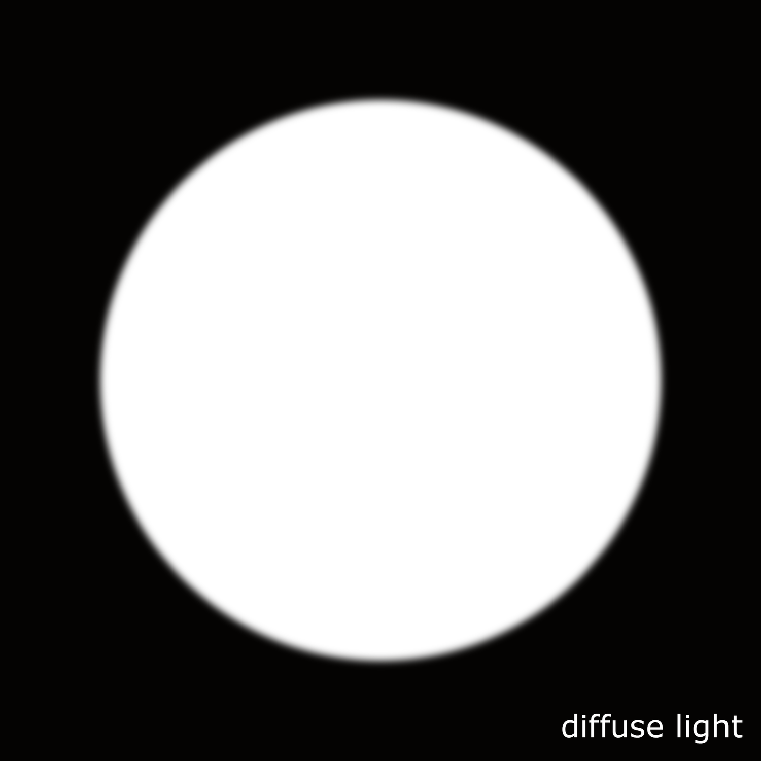
Diffuse light and soft light are not the same. When we talk about soft lighting we are talking about soft shadows. When we mention diffuse light we are talking about the distribution of the light, equally distributed along its surface.
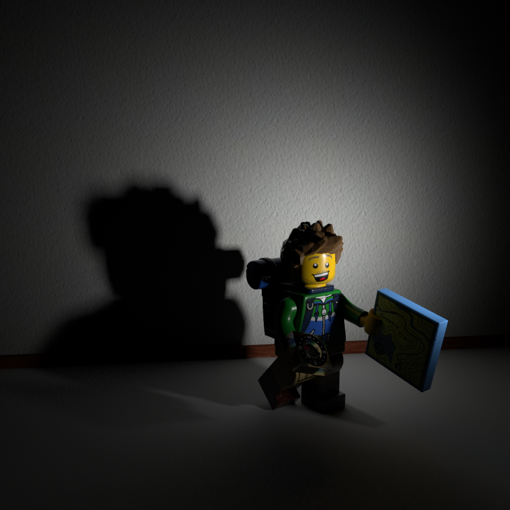
Some 3D samples with Legos.
- Here the character is being lit by a small lighting source, smaller than the character itself and placed far from the subject. We get hard light, hard shadows.

- Here we have a bigger lighting source, pretty much same size as the character and placed close to it. We get soft lighting, soft shadows.

- This is a big lighting source, much bigger than the subject. We now get extra soft lighting, losing the shape of the shadows.

- Now the character is being lit by the sun. The sun is a huge lighting source but being placed far far away from the subject it behaves like a small lighting source generating hard light.

- Finally there is another example of very hard light caused by the flash of the camera, another very powerful and concentrated point of light placed very close to the subject. You can get this in 3D reducing a lot the spread value of the light.
- Now a couple of images for specular and diffuse light.

From scan to asset /
In this video I will show you my process to convert 3D scans into assets ready for production. I believe the audio is in Spanish so, feel free to mute it or try to learn some Cervantes language :)
Meshlab polygon reduction /
Meshlab is probably the only available solution (proprietary Lidar software doesn't count) when you have to deal with very heavy poly count. I'm working with some complex terrains, some of them up to 50 million polys and Maya or Zbrush just can't handle that. I'm reducing the poly count considerably fast in Meshlab with its polygon reduction tools.
- This terrain has more than 16 million polys. Maya can't handle this very well, and Zbrush can't manage memory to even open it. Just import it in Meshlab.
- You will be using the Quadric Edge Collopse Decimation tool a lot.
- There are different strategies available, I like to use the percentage one. In this case by 0.5
- I'll be getting an 8 million poly terrain.
- I just run the tool one more time to get a 4 million terrain. I can work in Maya with this :)
Super Legos /
I just made this super hero Legos for an upcoming Arnold course that I'm developing for elephant vfx.
Look-dev scene of the characters.
IBL pack 0001 /
IBL pack 0001 is available for purchase.
30 different lighting situations ready to use in Maya 2017 and Arnold.
Just import your 3D assets and start look-deving and lighting.
Detailed information here.
Legos /
Having some fun with these small guys.
I will try to do a couple of these a month.
On-set tips: The importance of high frequency detail /
Quick tip here. Whenever possible use some kind of high frequency detail to capture references for your assets. In this scenario I'm scanning with photos this huge rock, with only 50 images and very bad conditions. Low lighting situation, shot hand-held, no tripod at all, very windy and raining.
Thanks to all the great high frequency detail on the surface of this rock the output is quite good to use as modeling reference, even to extract highly detailed displacement maps.
Notice in the image below that I'm using only 50 pictures. Not much you might say. But thanks to all the tiny detail the photogrammetry software does very well reconstructing the point cloud to generate the 3D model. There is a lot of information to find common points between photos.
The shooting pattern couldn't be more simple. Just one eight all around the subject. The alignment was completely successfully in Photoscan.
As you can see here, even with a small number of photos and not the best lighting conditions, the output is quite good.
I did an automatic retopology in Zbrush. I don't care much about the topology, this asset is not going to be animated at all. I just need a manageable topology to create a nice uv mapping and reproject all the fine detail in Zbrush and use it later as displacement map.
A few render tests.
UV to Mesh /
Mi friend David Munoz Velazquez just pointed me to this great script to flatten geometries based on UV Mapping, pretty useful for re-topology tasks. In this demo I use it to create nice topology for 3D garments in Marvelous Designer. Then I can apply any new simulation changes to the final mesh using morphs. Check it out.
Clarisse shading layers: Crowd in 5 minutes /
One feature that I really like in Clarisse are the shading layers. With them you can drive shaders based on naming convention or location of assets in the scene. With this method you can assign shaders to a very complex scene structure in no time. In this particular case I'll be showing you how to shade an entire army and create shading/texturing variations in just a few minutes.
I'll be using an alembic cache simulation exported from Maya using Golaem. Usually you will get thousand of objects with different naming convention, which makes the shading assignment task a bit laborious. With shading layer rules in Clarisse we can speed up a lot this tedious process
- Import an alembic cache with the crowd simulation through file -> import -> scene
- In this scene I have 1518 different objects.
- I'm going to create an IBL rig with one of my HDRIs to get some decent lighting in the scene.
- I created a new context called geometry where I placed the army and also created a ground plane.
- I also created another context called shaders where I'm going to place all my shaders for the soldiers.
- In the shaders context I created a new material called dummy, just a lambertian grey shader.
- We are going to be using shading layers, to apply shaders globally based on context and naming convention. I created a shading layers called army (new -> shading layer).
- With the pass (image) selected, select the 3D layer and apply the shading layer.
- Using the shading layer editor, add a new rule to apply the dummy shader to everything in the scene.
- I'm going to add a rule for everything called heavyArmor.
- Then just configure the shader for the heavyArmour with metal properties and it's correspondent textures.
- Create a new rule for the helmets and apply the shader that contains the proper textures for the helmets.
- I keep adding rules and shaders for different parts of the sodliers.
- If I want to create random variation, I can create shading layers for specific names of parts or even easier and faster, I can put a few items in a new context and create a new shading rule for them. For the bodies I want to use caucasian and black skin soldiers. I grabbed a few bodies and place them inside a new context called black. Then create a new shading rules where I apply a shader with different skin textures to all the bodies in that context.
- I repeated the same process for the shields and other elements.
- At the end of the process I can have a very populated army with a lot of random texture variations in just a few minutes.
- This is how my shading layers look like at the end of the process.
UDIM workflow in Nuke /
Texture artists, matte painters and environment artists often have to deal with UDIMs in Nuke. This is a very basic template that hopefully can illustrate how we usually handle this situation.
Cons
- Slower than using Mari. Each UDIM is treated individually.
- No virtual texturing, slower workflow. Yes, you can use Nuke's proxies but they are not as good as virtual texturing.
Pros
- No paint buffer dependant. Always the best resolution available.
- Non destructive workflow, nodes!
- Save around £1,233 on Mari's license.
Workflow
- I'll be using this simple footage as base for my matte.
- We need to project this in Nuke and bake it on to different UDIMs to use it later in a 3D package.
- As geometry support I'm using this plane with 5 UDIMs.
- In Nuke, import the geometry support and the footage.
- Create a camera.
- Connect the camera and footage using a Project 3D node.
- Disable the crop option of the Project 3D node. If not the proejctions wouldn't go any further than UV range 0-1.
- Use a UV Tile node to point to the UDIM that you need to work on.
- Connect the img input of the UV Tile node to the geometry support.
- Use a UV Project node to connect the camera and the geometry support.
- Set projection to off.
- Import the camera of the shot.
- Look through the camera in the 3D view and the matte should be projected on to the geometry support.
- Connect a Scanline Render to the UV Project.
- Set the projection model to UV.
- In the 2D view you should see the UDIM projection that we set previously.
- If you need to work with a different UDIM just change the UV Tile.
- So this is the basic setup. Do whatever you need in between like projections, painting and so on to finish your matte.
- Then export all your UDIMs individually as texture maps to be used in the 3D software.
- Here I just rendered the UDIMs extracted from Nuke in Maya/Arnold.