Introduction to Gaffer part 04 where I talk mostly about volumes. I also mention a few things about good practices while look-deving “fetchin” textures and what not.
look-dev
Houdini as scene assembler part 03 /
In this post I will talk about using texture bitmaps and subdivision surfaces.
I have a material network with a couple of shaders, one for the body of this character and another one for the rest. If using Arnold I would have a shop network.
To bring texture bitmaps I use texture nodes when working with Mantra and image nodes when working with Arnold. The principled shader has tabs with inputs for textures. I rarely use these, I always create nodes to take care of the texturing. At the end of the day I never use only one texture per channel. More of this in future posts.
In Mantra, textures are multiplied by the albedo color. Be careful with this.
With Mantra, this is the UDIM tag textureName.%(UDIM)d.exr with arnold textureName.<UDIM>.exr
There is a triplanar node that can be used with Arnold and a different one called UV triplanar projection for Mantra. I don’t usually work without UVs, but these nodes can be useful when working with terrains or other large surfaces.
To subdivide geometry, at object level you can just go to the Arnold tab and select the type of subdivision and the amount. If you need to subdivide only a few parts of you alembic asset, create an unpack node (transfer attributes and groups) and then a subdivide node. This works with both Mantra and Arnold, although there is a better way of doing this with Arnold. We will talk about it in the future.
Introduction to Gaffer 03 /
Introduction to Gaffer part 03, where I show you how to use references, AOVs, batch rendering, displacement maps, other useful tools.
Houdini as scene assembler part 02 /
In the previous post I showed you how to load alembic caches using the file node and then change the viewport visualization to bounding box. This is good enough if you are let's say look-deving a character. If you want to load a heavy alembic cache, like a very detailed city with a lot of buildings, or a huge spaceship, you might want to use a different approach.
Instead of using a file node, it is better to use the alembic node to load you assets, and then set the option Load As: alembic delayed load primitives, and display as bounding box. This isn't actually loading the geometry in memory and it will be way more efficient down the line.
In this post I'm just talking about shading assignment in Houdini.
The easiest and more simple way to assign shaders is by selecting the asset node in the /obj context and assign a shader in the render tab. Your Mantra shaders should be placed in the /mat context and your Arnold shaders in the /shop context as /mat is not fully supported yet.
In the /mat context you can just go and create a Mantra Principled Shader. For Arnold, it is better to create an arnold shader network and then any arnold shader inside connected to the surface input.
Houdini doesn't have an isolation mode for shading components like Maya (as far as I know) but you can drag and drop shaders and textures onto the viewport or IPR while look-deving. This only works in the /mat context (again, as far as I know).
Another way of assigning shaders is creating material nodes inside of the alembic node. This material nodes can be assigned to different parts of your asset using wildcards. To assign multiple materials you can create different tabs in the material node or you can just concatenate material nodes (which I prefer). This technique works with both Mantra and Arnold.
You will find yourself most of the time creating material networks (Mantra) or shop networks (arnold) containing all the shaders of your asset. In a lighting shot you will end up with different subnetworks for each asset on the shot.
This subnetworks of shaders can be place at the /obj level or inside of the alembics containing your assets.
Another clever way of assignment shaders is using the data tree -> object appearance. This only works at object level. If you want to go deeper in your alembic asset, you need to add first a node called packed edit. Then in the data tree you will have access to all the different parts of your asset.
There is another way of controlling looks in Houdini, and that is using the material style sheets. We will cover this tool in future posts.
A bit more of gaffer /
Keep playing with gaffer and keep discovering how to do stuff that I’m used to do in other software.
Introduction to gaffer /
By gaffer hq: Gaffer is a free, open-source, node-based VFX application that enables look developers, lighters, and compositors to easily build, tweak, iterate, and render scenes. Built with flexibility in mind, Gaffer supports in-application scripting in Python and OSL, so VFX artists and technical directors can design shaders, automate processes, and build production workflows.
With hooks in both C++ and Python, Gaffer's readily extensible API provides both professional studios and enthusiasts with the tools to add their own custom modules, nodes, and UI.
The workhorse of the production pipeline at Image Engine Design Inc., Gaffer has been used to build award-winning VFX for shows such as Jurassic World: Fallen Kingdom, Lost in Space, Logan, and Game of Thrones.
Houdini as scene assembler, part 01 (of many) /
It’s been a while since I used Houdini at work, the very first time I used Houdini on a show it was while working on Happy Feet 2, it was our main scene assembler for the show. Look-dev, lighting and rendering was all done in Houdini and 3Delight.
From there I never used Houdini again until I was working on Geostorm at Dneg. Most of the shots were managed with Houdini and PrMan. That is all my experience with Houdini in a professional environment. No need to say that I have only used Houdini for assembly tasks, look-dev, lighting and rendering, nothing like fx or other fancy stuff.
The common thing between the two shows where I used Houdini as assembler is that we had pretty neat tools to take care of most of the steps through the pipeline. Becasue of that I can’t barely use Houdini out of the box, so I’m going to try to learn how to use it and share it here for future reference.
During my time working at facilities like MPC, Dneg or Framestore, I have used different scene assemblers like Katana, Clarisse or other propietary tools. My goal is to extrapolate my knowledge and experience using those software to Houdini. I’m pretty sure that I’d be using tools and techniques in the wrong way just because Houdini has a different philosophy than other tools or just because my lack of knowledge in general about Houdini and proceduralism. But anyway, I’ll try to make it work, if you see anything that I’m doing terribly wrong, please let me know, I’ll be listening.
I’ll be posting about stuff that I’m dealing with in no particular order but always assembly oriented, do not expect to see here anything related with fx or more “traditional” use of Houdini. Most of the stuff is going to be very basic, specially at the beginning but please bare with me, it will get more interesting in the future.
If you are assembling a scene one of the first steps it would be to bring all your assets from other applications. You can of course generate content in Houdini but usually most of you assets will be created in other packages, being Maya the most common one. So I guess the very first thing you’d have to deal with is how to import alembic caches. If you are working in a vfx facility chances of having automated tools to setup your shots for you are pretty high. Launching Houdini from a context in a terminal will take care of everything. If you are at home or starting to use Houdini in a vfx boutique you will have to setup your shots manually. There are clever and easy ways to create Houdini templates for your show/shot but we will leave this topic for future posts.
To bring your assets as alembic caches just create a file node, step inside and replace the existing file for another file node pointing to your alembic cache, or just use the existing file node and change the path to read you alembic cache.
If you are look-deving a character lets say, it is completely fine to look at the full geometry in the viewport. If you are assembling a big scene like a city or a space ship you’d probably want to change your viewport settings to something like bounding boxes. There are better ways of dealing with bounding box without loading the geo, more to come soon.
Assets are usually complex and we try to keep everything tidy and organised by naming everything properly and structuring groups and hierarchies in a particular way that makes sense for our purposes. The unpack node will allow you to access to all the different parts and componentes of the alembic caches and to perform different operations later on. The groups can be selected based on the hierarchies created in Maya or based on wildcards. It is extremely important to use a clever naming and structuring groups following certain logic to make the assembly process easier and faster.
The blast node will help you also to access to the information contained in the alembic cache and remove whatever you don’t need to use for a particular operation. You can also invert the selection to keep the items that you wrote in the group field and get rid of the rest.
The group node is another very useful node to point to different groups in your alembic caches. Again based on Maya grouping and wildcards.
That is it for now in that sense, there are many ways to manipulate alembic caches but we don’t need to talk about that just yet. In these first posts I will be talking mostly about bringing assets, working with textures and look-dev. That is the first step for assembling a shot, we need assets ready to travel trough the pipeline.
Uv mapping is key for us, a lot of tasks performed in Houdini use procedural UVs or no UVs at all. This is not the case for us. Asset always have proper UV mapping. Generally speaking you will do all the UV related tasks in Maya, UV Layout or similar tools. In order to see the UVs in Houdini we need to unpack the alembic cache first, then we will be able to press “5” and look at the UVs.
Use a quick uv shade node to display a checkered texture in the viewport. You can easily change the size of the checker or use a different texture. There is also a group field that you can use for filtering.
Not ideal but if you are working on extremely simple assets like walls, grounds, maybe terrains, it is totally fine to create the UVs in Houdini. Houdini UV tools are not the best but you will find yourself using them at some point. The uv texture node crates basic projections like cylindrical, orthographic, etc.
The uv unwrap node create automatic UVs based on projection planes.
The uv layout node is a tools for packing your UVs. Using a fixed scale you can distribute the UVs in different UDIMs.
The auto uv node is actually pretty good. It is part of the game development tools shipped with Houdini. You need to activate this package first, just go the shelf, click on the plus button and look for game development tools. Then click on the icon update toolset to get the latest version.
The auto uv tools has different methods for UVing and for packing, it is worth trying them, it works really well specially with messy objects.
The uv transform node deals with anything related to moving, translating and rotating UVs. You don’t really want to do this here in Houdini, but if you have to, this is the tool. I use it a lot if I need to re-distribute UDIM tiles.
Attribute create node (with the following parameters) allos you to create a parameter to move UVs to a specific UDIM. Then add a uv layout node and set the packing method to UDIM attribute.
Ricoh Theta for image acquisition in VFX /
This is a very quick overview of how I use my tiny Ricoh Theta for lighting acquisition in VFX. I always use one of my two traditional setups for capturing HDRI and bracketed textures but on top of that, I use a Theta as backup. Sometimes if I don't have enough room on-set I might only use a Theta, but this is not ideal.
There is no way to manually control this camera, shame! But using an iPhone app like Simple HDR at least you can do bracketing. Still can't control it, but it is something.
As always capturing any camera data, you will need a Macbeth chart.
For HDRI acquisition it is always extremely important to have good references for you lighting distribution, density, temperature, reflection and shadow. Spheres are a must.
For this particular exercise I'm using a Mini Manfrotto tripod to place my camera above 50cm from the ground aprox.
This is the equitectangular map that I got after merging 7 brackets generated automatically with the Theta. There are 2 major disadvantages if you compare this panorama with the ones you typically get using a traditional DSLR + fisheye setup.
- Poor resolution, artefacts and aberrations
- Poor dynamic range
I use HDR merge pro in Photoshop to merge my brackets. It is very fast and it actually works. But never use Photoshop to work with data images.
Once the panorama has been stitched, move to Nuke to neutralise it.
Start by neutralising the plate.
Linearization first, followed by white balance.
Copy the grading from the plate to the panorama.
Save the maps, go to Maya and create an IBL setup.
The dynamic range in the panorama is very low compared with what we would have if were using a traditional DSLR setup. This means that our key light is not going to work very well I'm afraid.
If we compare the CG against the plate, we can easily see that the sun is not working at all.
The best way to fix this issue at this point is going back to Nuke and remove the sun from the panorama. Then crop it and save it as a HDR texture to be mapped in a CG light.
Map the HDR texture to a area light in Maya and place it accordingly.
Now we should be able to match the key light much better.
Final render.
Quick and dirty free IBLs /
Some of my spare IBLs that I shot while ago using a Ricoh Theta. They contain around 12EV dynamic range. Resolution is not pretty good but it stills holds up for look-dev and lighting tasks.
Feel free to download the equirectangular .exrs here.
Please do not use in commercial projects.
Cafe in Barcelona.
Cafe in Barcelona render test.
Hobo hotel.
Hobo hotel render test.
Campus i12 green room.
Campus i12 green room render test.
Campus i12 class.
Campus i12 class render test.
Chiswick Gardens.
Chiswick Gardens render test.
Mixing displacement and multiple bump maps /
A very common situation when look-deving an asset is combining various displacement and bump maps. Having them in different texture maps gives you the possibility to play with them and making very fast changes without going back to Mari and Zbrush and waste a lot of time going back and forward until reaching the right look. You also want to keep busy your look-dev team, of course.
While ago I told you how to combine different displacement maps coming from different sources, today I want to show you how to combine multiple bump maps, with different scales and values. This is a very common situation in vfx, I would say every single asset has at least one displacement layer and one bump layer, but usually, you would have more than one. This is how you can combine multiple bump layers in Maya/Arnold.
- The first thing I'm going to do is add a displacement layer. To make this post easy I'm using a single displacement layer. Refer back to the tutorial I mentioned previously on this post to mix more than one displacement layer.
- Now connect your first bump map layer as usual. Connecting the red channel to the bump input of the shader.
- in the hypershade create a file texture for your second bump layer. In this case a low frequency noise.
- Create an avergage node and two multiply nodes.
- Connect the red channel of the first bump layer to the input 1 of the multiply node. Control the intensity of this layer with the input 2 of the multiply node.
- Repeat with previous step with the second bump layer.
- Connect the outputs of both multiply nodes to the inputs 3D0 and 3D1 of the average node.
- It is extremely important to leave the bump depth at 1 in order to make this work.
Cryptomatte in Fusion /
I'm using Fusion at home and trying to find workarounds for my texturing, look-dev and lighting pipeline. A must thing to have these days is cryptomatte, I can't see any work done without it, going back to ID passes is not an option.
- To install it properly, you need to place the 3 .lua files in the same directory where your Fusion executable is located.
- The fuse file should be places inside of your fuses folder and then blackmagic folder.
- Apparently at the time of writing this, there is a bug with cryptomatte for Fusion not reading properly the cryptomatte data inside of a multi channel .exr
- Rendering the cryptomate data in individual .exr is the best way to work.
- Having the cryptomatte in it's own .exr will save the pain of shuffle channels in Fusion.
- Use the add button and the color picker in the viewport to isolate parts of your render in the alpha channel.
Iron Patriot finished /
Let's say it is finished for now. It will be the asset used in my next texturing and look-dev course.
Iron Patriot wip 02 /
Another wip of this character. More to come.
Iron Patriot wip 01 /
I'm working on a texturing and look-dev course for elephant vfx and this is the asset that I'm preparing. Just an arm for now but I guess it's time to show you guys something. Stay tuned.
Hard light / soft light / specular light / diffuse light /
These days we are lucky enough to apply the same photographic and cinematographic principles to our work as visual effects artists lighting shots. That's why we are always talking about cinematography and cinematic language. Today we are going to talk about some very common techniques in the cinematography world: hard light, soft light, specular light and diffuse light.
The main difference between hard light and soft light do not eradicate in the light itself but in the shadows. When the shadow is perfectly defined and opaque we talk about hard light. When the shadows are diffuse we called it soft lighting, the shadows will also be less opaque.
Is there any specific lighting source that creates hard or soft lighting? The answer is no. Any light can create hard or soft lighting depending on two factors.
- Size: Not only the size of the practical lighting source but also the size in relationship with the subject that is being illuminated.
- Distance: In relation to the subject and the placement of the lighting source.
Diffraction refers to various phenomena that occur when a wave encounters an obstacle or a slit. It is defined as the bending of light around the corners of an obstacle or aperture into the region of geometrical shadow of the obstacle.

When a light beam impacts on the surface of an object, if the size of the lighting source is similar to the size of the object, the light beam will go parallel and get slightly curved towards the interior.

If the size of the lighting source is smaller than the object or it is placed far away from it, the light beam won't bend creating very hard and defined shadows.

If the lighting source is bigger than the subject and it's placed near of it, the light beam will get curved a lot generating soft shadows.

If the lighting source is way bigger than the subject and it's place near of it, the light beam will be curved a lot, even they will get mixed at some point. Consequently the profile of the subject will not be represented in the shadows.

If a big lighting source is placed very far of the subject, its size will be altered in relation with the subject, and its behavior will be the same as a small lighting source, generating hard shadows. The most common example of this is the sun. It is very far but still generates hard lighting. Only on cloudy days the sun lights gets diffused by the clouds.
In two lines
- Soft light: Big lighting sources and or close to the subject.
- Hard light: Small lighting sources and or far from the subject.
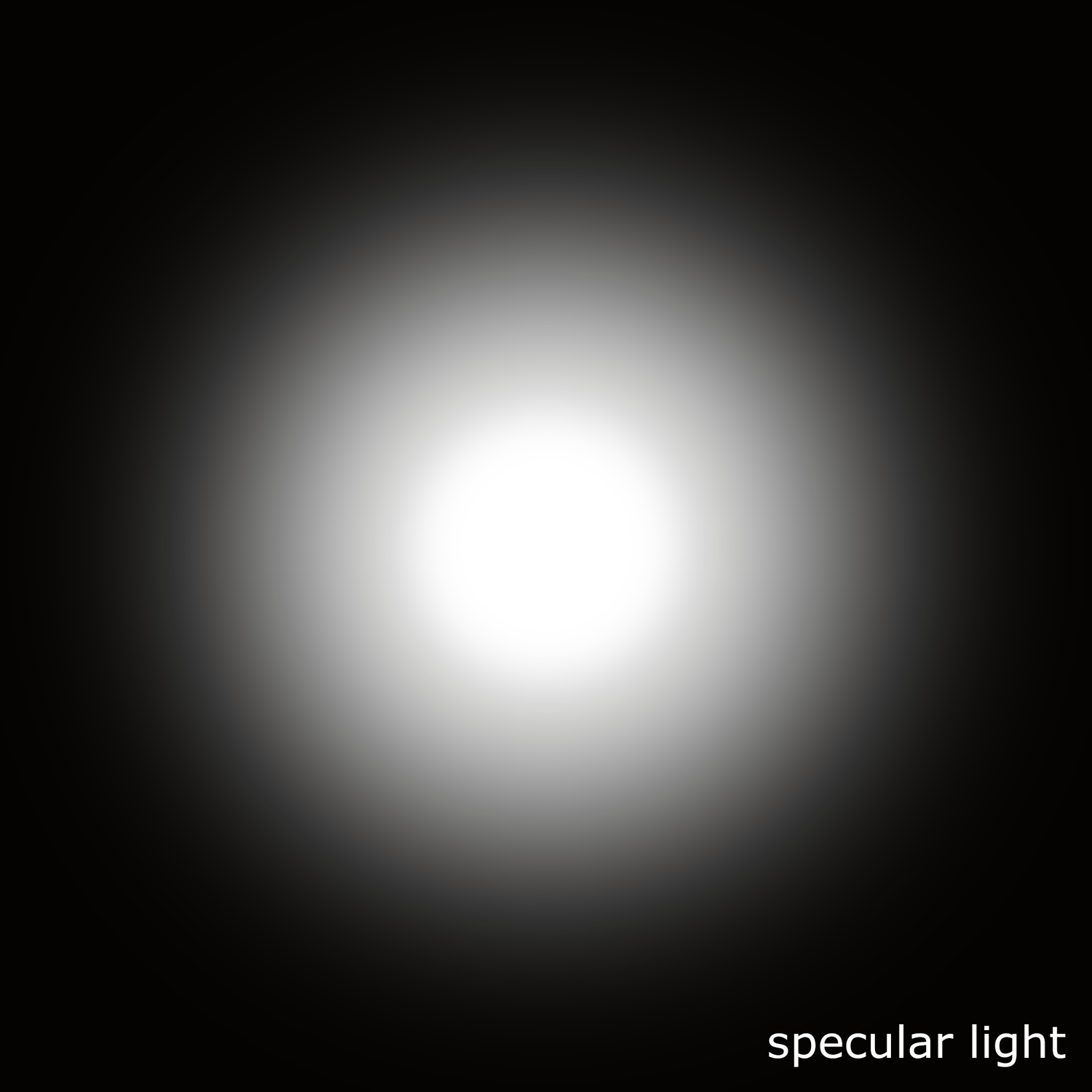
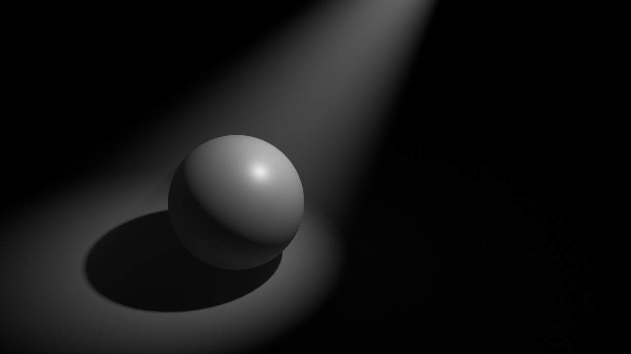
Specular light: Lighting source very powerful in the center that gradually loses energy toward its extremes. Like a traditional torch. It generates very exposed and bright areas in the subject. Like the lights used in photo calls and interviews.
Diffuse light: Lighting source with uniform energy all over its surface. The lighting tends to be more compensated when it hits the subject surface.
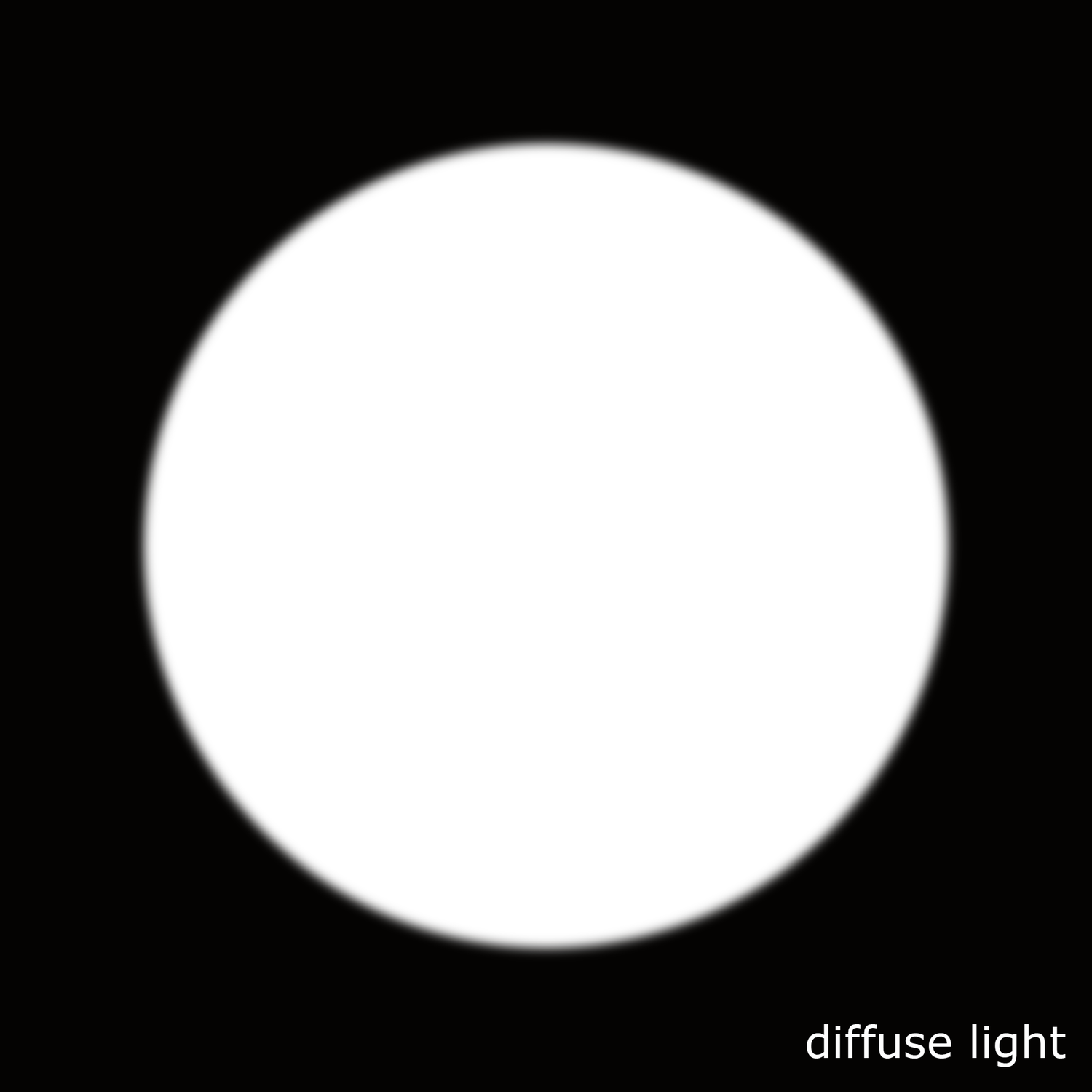
Diffuse light and soft light are not the same. When we talk about soft lighting we are talking about soft shadows. When we mention diffuse light we are talking about the distribution of the light, equally distributed along its surface.
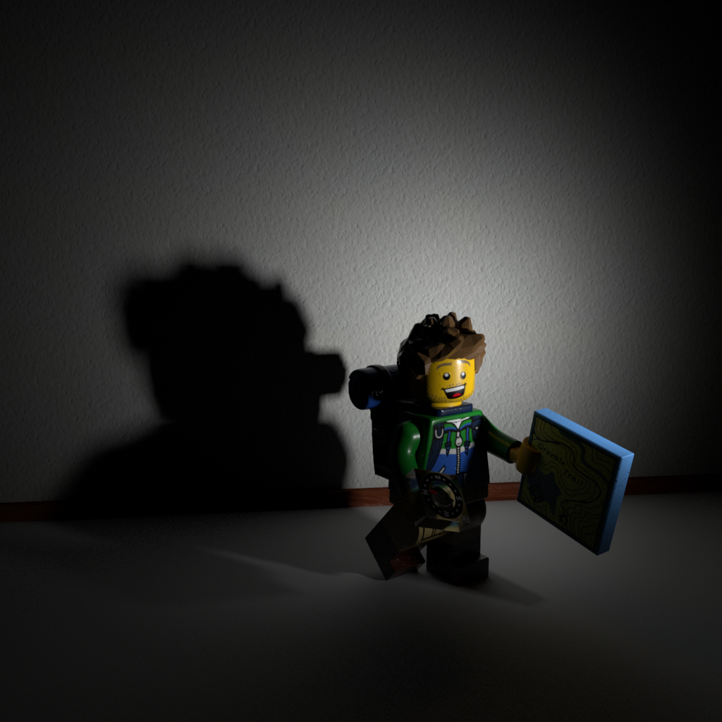
Some 3D samples with Legos.
- Here the character is being lit by a small lighting source, smaller than the character itself and placed far from the subject. We get hard light, hard shadows.

- Here we have a bigger lighting source, pretty much same size as the character and placed close to it. We get soft lighting, soft shadows.

- This is a big lighting source, much bigger than the subject. We now get extra soft lighting, losing the shape of the shadows.

- Now the character is being lit by the sun. The sun is a huge lighting source but being placed far far away from the subject it behaves like a small lighting source generating hard light.

- Finally there is another example of very hard light caused by the flash of the camera, another very powerful and concentrated point of light placed very close to the subject. You can get this in 3D reducing a lot the spread value of the light.
- Now a couple of images for specular and diffuse light.

Clarisse shading layers: Crowd in 5 minutes /
One feature that I really like in Clarisse are the shading layers. With them you can drive shaders based on naming convention or location of assets in the scene. With this method you can assign shaders to a very complex scene structure in no time. In this particular case I'll be showing you how to shade an entire army and create shading/texturing variations in just a few minutes.
I'll be using an alembic cache simulation exported from Maya using Golaem. Usually you will get thousand of objects with different naming convention, which makes the shading assignment task a bit laborious. With shading layer rules in Clarisse we can speed up a lot this tedious process
- Import an alembic cache with the crowd simulation through file -> import -> scene
- In this scene I have 1518 different objects.
- I'm going to create an IBL rig with one of my HDRIs to get some decent lighting in the scene.
- I created a new context called geometry where I placed the army and also created a ground plane.
- I also created another context called shaders where I'm going to place all my shaders for the soldiers.
- In the shaders context I created a new material called dummy, just a lambertian grey shader.
- We are going to be using shading layers, to apply shaders globally based on context and naming convention. I created a shading layers called army (new -> shading layer).
- With the pass (image) selected, select the 3D layer and apply the shading layer.
- Using the shading layer editor, add a new rule to apply the dummy shader to everything in the scene.
- I'm going to add a rule for everything called heavyArmor.
- Then just configure the shader for the heavyArmour with metal properties and it's correspondent textures.
- Create a new rule for the helmets and apply the shader that contains the proper textures for the helmets.
- I keep adding rules and shaders for different parts of the sodliers.
- If I want to create random variation, I can create shading layers for specific names of parts or even easier and faster, I can put a few items in a new context and create a new shading rule for them. For the bodies I want to use caucasian and black skin soldiers. I grabbed a few bodies and place them inside a new context called black. Then create a new shading rules where I apply a shader with different skin textures to all the bodies in that context.
- I repeated the same process for the shields and other elements.
- At the end of the process I can have a very populated army with a lot of random texture variations in just a few minutes.
- This is how my shading layers look like at the end of the process.
RAW lighting and albedo AOVs in Arnold /
If you are new to Arnold you are probably looking for RAW lighting and albedo AOVs in the AOV editor. And yes you are right, they are not there. At least when using AiStandard shaders.
The easiest and fastest solution would be to use AlShaders, they include both, RAW lighting and albedo AOVs. But if you need to use AiStandard shaders, you will have to create your own AOVs quite easily).
- In this capture you can see available AOVs for RAW lighting and albedo for the AlShaders.
- If you are using AiStandard shaders you won't see those AOVs.
- If you still want/need to use AiStandard shaders, you will have to render your beauty pass with the standard AOVs and utility passes and you will have to create the albedo pass by hand. You can easily do this replacing AiStandard shaders by Surface shaders.
- if we have a look at them in Nuke they will look like these.
- If we divide the beauty pass by the albedo pass we will get the RAW lighting.
- We can now modify only the lighting without affecting the colour.
- We can also modify the colour component without modifying the lighting.
- In this case I'm color correcting and cloning some stuff in the color pass.
- With a multiply operation I can combine both elements again to obtain the beauty render.
- If I disable all the modification to both lighting and color, I should get exactly the same result as the original beauty pass.
- Finally I'm adding a ground using my shadow catcher information.
UVs AOV in Arnold Render /
This video was created for elephantvfx.com which means that it's only available in Spanish. But you can mute it and follow what I do visually :)
I basically explain how to render UVs AOVs in a couple of different ways using Maya and Arnold.
Hulkbuster /
I've been working on this character for a texturing and look-dev course that I'll be presenting pretty soon. Hope you like it.
Central Saint Martins free HDRI /
I shot another HDRI for Akromatic that you can download for free for your look-dev and lighting tests.
Check it out at the Akromatic website.