I shot a new HDRI panorama for 3D Lighting and Look-development for akromatic.com
Check it out here, it's free!
Texturing and look-dev at TD-U /
Third call for my texturing and look-development course at TD-U.
It is an 8 week workshop starting at May 25th to July 20th, 2015.
All the info here.
RGB masks /
We use RGB masks all the time in VFX, don't we?
They are very handy and we can save a lot of extra texture maps combining 4 channels in one single texture map RGB+A.
We use them to mix shaders in look-dev stage, or as IDs for compositing, or maybe as utility passes for things like motion blur o depth.
Let's see how I use RGB masks in my common software: Maya, Clarisse, Mari and Nuke.
Maya
- I use a surface shader with a layered texture connected.
- I connect all the shaders that I need to mix to the layered texture.
- Then I use a remapColor node with the RGB mask connected as mask for each one of the shaders.
This is the RGB mask that I'm using.
- We need to indicate which RGB channel we want to use in each remapColor node.
- Then just use the output as mask for the shaders.
Clarisse
- In Clarisse I use a reorder node connected to my RGB mask.
- Just indicate the desired channel in the channel order parameter.
- To convert the RGB channel to alpha just type it in the channel order field.
Mari
- You will only need a shuffle adjustment layer and select the required channel.
Nuke
- You can use a shuffle node and select the channel.
- Or maybe a keyer node and select the channel in the operation parameter. (this will place the channel only in the alpha).
Akromatic base /
As VFX artists we always need to place our color charts and lighting checkers (or practical spheres) somewhere on the ground while shooting bracketed images for panoramic HDRI creation. And we know that every single look-development and / or lighting artist is going to request at least all these references for their tasks back at the facility.
I'm tired of seeing my VFX peers working on set placing their lighting checkers and color charts on top of their backpacks or hard cases to make them visible on their HDRIs. In the best scenario they usually put the lighting checkers on a tripod with it's legs bended.
I've been using my own base to place my lighting checkers and all my workmates keep asking me about it, so it's time to make it available for all of you working on set on a daily basis.
The akromatic base is light, robust and made of high quality stainless steel. It is super simple to attach our lighting checkers to it and keep them safe and more important, visible in all your images. Moving all around the set with your lighting checkers and color charts from take to take is now simple, quick and safe.
The akromatic base is compatible with our lighting checkers "Mono" and "Twins".
New features in UV Layout v2.08.06 /
The new version of UV Layout v2.08.06 was released a few weeks ago and it is time to talk about some of the new exciting features. I'll be mentioning also old tools and features from previous versions that I'm starting to use now and didn't use much before.
- Display -> Light: It changes the way lighting affects the scene, it is very useful when some parts are occluded in the checking window. It has been there for a while but I just started using it not long ago.
- Settings -> F1 F2 F3 F4 F5: This buttons will allow you to create shortcuts for other tools, so instead of using the menus you can map one of the function keys to use that tool.
- Preferences -> Max shells: This option will allow you to increase the number of shells that UV Layout can handle. This is a very very important feature. I use it a lot specially when working with crazy data like 3D scans and photogrammetry.
- Flatten multiple objects at once: It didn't work before but it does now. Just select a bunch of shells and press "r".
- Pack -> Align shells to axes: Select your shells, enable the option "align shells to axes" and click on pack.
- Pack by tiles: Now UDIM organization can be done inside UV Layout. Just need to specify the number of UDIMs in X and Y and click on pack.
- Pack -> Move, scale, rotate: As part of UDIM organization now you can move whole tiles around.
- Trace masks: This is a great feature! Specially useful if you already have a nice UV mapping and suddenly need to add more pieces to the existing UV layout. Just mask out the existing UVs and place the new one in the free space. To do so just place in boxes de new UVs and go to displace -> trace and select your mask. Click on pack and that's it, your new UVs will be placed in the proper space.
Segment marked polys: This is great specially for very quick UV mapping. Just select a few faces click on segment marked polys and UV Layout will create flat projections for them.
- Set size: This is terrific! one of my favourite options. Make the UVs for one object and check the scale under Move/Scale/Rotate -> Set size. Then use that information in the preferences. If later you import a completely different objec, UV Layout will be using the size of the previous object to match the scale between objects. That means all your objects will have exactly same scale and resolution UVs wise. Amazing for texture artists!
- Pin edges: A classic one. When you are relaxing a shell and want to keep the shape, press "pp" on the outer edges to pin them. Then around the eyes or other interior holes press "shift+t" around the edges. Then you can relax the shell keeping the shape of the object.
- Anchor points: Move one point on the corner with "ctrl+MMB" and press "a" to make it anchor point. Then move another point in the opposite corner and do the same. Then press "s" on top of each anchor point. Then "ss" on any point in between the anchors to align them. Combining this with pinned edges will give you perfect shapes.
VFX Lighting workshop in Madrid /
Next 16th and 17th of May I'll be in Fictizia School in Madrid talking about VFX Lighting and Image Acquisition. Come by if you are in town!
All the info here.
Clarisse UV interpolation /
When subdividing models in Clarisse for rendering displacement maps, the software subdivides both geometry and UVs. Sometimes we might need to subdivide only the mesh but keeping the UVs as they are originally.
This depends on production requirements and obviously on how the displacement maps were extracted from Zbrush or any other sculpting package.
If you don't need to subdivide the UVs first of all you should extract the displacement map with the option SmoothUV turned off.
Then in Clarisse, select the option UV Interpolation Linear.
By default Clarisse sets the UVs to Smooth.
You can easily change it to Linear.
Render with smooth UVs.
Render with linear UVs.
Mission Impossible 5 Teaser Trailer /
The very first teaser trailer for Mission Impossible 5 is out!
I've been working on this project for a while :)
London Bridge Underground IBL /
I shot a new high resolution HDRI panorama for akromatic.com
It is completely free and it comes with clean plates, lighting and color references and calibrated IBL light-rigs for arnold and v-ray.
Check it out here.
Cat's food - quick breakdown /
The other I published a very simple image that I did just to test a few things. A couple of photographic techniques, my new Promote Control, procedural masks done in Substance Designer and other grading related stuff in Nuke. Just a few things that I wanted to try for a while.
This is a quick breakdown, as simple as the image itself.
- The very first thing that I did was taking a few stills of the plate that I wanted to use as background to place my CG elements. From the very beginning I wanted to create an extremely simple image, something that I could finish in a few hours. With that in mind I wanted to create a very realistic image, and I'm not talking about lighting or rendering, I'm talking about the general feeling of being realistic. With bad framing, bad compositing, with total lack of lighting intention, with no cinematic components at all. The usual bad picture that everyone posts in social networks once in a while, without any narrative or visual value.
- In order to create good and realistic CG compositions we need to gather a lot of information on-set. In this case everything is very simple. When you take pictures you can read the meta-data later in the computer. This will help to see the size of the sensor of your digital camera and the focal used to take the pictures. With this data we can replicate the 3D camera in Maya or any other 3D package.
- It is also very important to get good color references. Just using a Macbeth Chart we can neutral grade the plate and everythign we want to re-create from scratch in CG.
- The next step is to gather lighting information on-set. As you can imagine everything is so simple because this is a very tiny and simple image. There are not practical lights on-set just a couple of tiny bulbs on the ceiling. But they don't affect the subject so don't worry much about them. The main lighting source is the sun (although it was pretty much cloudy) coming through the big glass door on the right side of the image, out of camera. So we could say the lighting here is pretty much ambient light.
- With only an equirectangular HDRI we can easily reproduce the lighting conditions on set. We won't need CG lights or anything like that.
- This is possible because I'm using a very nice HDRI with a huge range. Linear ranges go up to 252.00000
- I didn't eve care about cleaning up the HDRI map. I left the tripod back there and didin't fix some ghosting issues. These little issued didn't affect at all my CG elements.
- It is very important to have lighting and color references inside the HDRI. If you pay attention you will see a Macbeth Chart and my akromatic lighting checkers placed in the same spot where the CG elements will be placed later.
- Once the HDRI is finished, it is very importante to have color and lighting references in the shot context. I took some pictures with the macbeth chart and the akromatic lighting checkers framed in the shot.
- Actually it is not exactly the same framing than the actual shot, but the placement of the checkers, the lighting source and the middle exposure remains the same.
- For this simple image we don't need to make any tracking or rotospocing work. This is a single frame work and we have a 90 degree angle between the floor and the shelf. With that in mind plus the meta-data from the camera reproducing the 3D camera is extremely simple.
- As you probably expected, modellin was very simple and basic.
- With this basic models I also tried to keep texturing very simple. Just found a few references on internet nad tried to match them as close as I could. Only needed 3 texture channels (diffuse, specular and bump). Every single object has a 4k texture map with only 1 UDIM. Didn't need more than that.
- As I said before, lighting wise I only needed an IBL setup, so simple and neat. Just an environment light with my HDRI connected to it.
- it is very important that your HDRI map and your plate share similar exposure so you can neutral grade them. Having same or similar exposure and Macbeth Charts in all your sequences is so simple to copy/paste gradings.
- Akromatic lighting checkers would help a lot to place correctly all the reflections and regulate lighting intensity. They would help also to establish the penumbra area and the behaviour of the lighting decay.
- Once the placement, intensity and grading ob the IBL are working fine, it is a good idea to render a "clay" version of the scene. This is a very smart way to check the behaviour of the shadows.
- In this particular example they work very well. This is because of the huge range that I have in my HDRI. With clampled HDRI this wouldn't be working that good and you would probably have to recreate the shadows using CG lights.
- The render was so quick. I don't know exactly but something around 4 or 5 minutes. Resolution 4000x3000
- Tried to keep 3D compositing simple. Just one render pass with a few AOV's. Direct diffuse, indirect diffuse, direct specular, indirect specular, refraction and 3 IDs to individually play with some objects.
- An this is it :)
Cat's food /
Quick and dirty render that I did the other day.
Just testing my Promote Control for bracketing the exposures for the HDRI that I created for this image. Tried to do something very simple, to be achieved in just a few hours. Trying to keep realism, tiny details, bad framing and total lack of lighting intention.
Just wanted to create a very simple and realistic image, without any cinematic components. At the end, that's reality, isn't it?
IBL and sampling in Clarisse /
Using IBLs with huge ranges for natural light (sun) is just great. They give you a very consistent lighting conditions and the behaviour of the shadows is fantastic.
But sampling those massive values can be a bit tricky sometimes. Your render will have a lot of noise and artifacts, and you will have to deal with tricks like creating cropped versions of the HDRIs or clampling values out of Nuke.
Fortunately in Clarisse we can deal with this issue quite easily.
Shading, lighting and anti-aliasing are completely independent in Clarisse. You can tweak on of them without affecting the other ones saving a lot of rendering time. In many renderers shading sampling is multiplied by anti-aliasing sampling which force the users to tweak all the shaders in order to have decent render times.
- We are going to start with this noisy scene.
- The first thing you should do is changing the Interpolation Mode to
MipMapping in the Map File of your HDRI.
- Then we need to tweak the shading sampling.
- Go to raytracer and activate previz mode. This will remove lighting
information from the scene. All the noise here comes from the shaders.
- In this case we get a lot of noise from the sphere. Just go to the sphere's material and increase the reflection quality under sampling.
- I increased the reflection quality to 10 and can't see any noise in the scene any more.
- Select again the raytracer and deactivate the previz mode. All the noise here is coming now from lighting.
- Go to the gi monte carlo and disable affect diffuse. Doing this gi won't affect lighting. We have now only direct lighting here. If you see some noise just increase the sampling of our direct lights.
- Go to the gi monte carlo and re-enable affect diffuse. Increase the quality until the noise disappears.
- The render is noise free now but it still looks a bit low res, this is because of the anti-aliasing. Go to raytracer and increase the samples. Now the render looks just perfect.
- Finally there is a global sampling setting that usually you won't have to play with. But just for your information, the shading oversampling set to 100% will multiply the shading rays by the anti-aliasing samples, like most of the render engines out there. This will help to refine the render but rendering times will increase quite a bit.
- Now if you want to have quick and dirt results for look-dev or lighting just play with the image quality. You will not get pristine renders but they will be good enough for establishing looks.
VFX footage input/output /
This is a very quick and dirty explanation of how the footage and specially colour is managed in a VFX facility.
Shooting camera to Lab
The RAW material recorded on-set goes to the lab. In the lab it is converted to .dpx which is the standard film format. Sometimes the might use exr but it's not that common.
A lot of movies are still being filmed with film cameras, in those cases the lab will scan the negatives and convert them to .dpx to be used along the pipeline.
Shooting camera to Dailies
The RAW material recorded on-set goes to dailies. The cinematographer, DP, or DI applies a primary LUT or color grading to be used along the project.
Original scans with LUT applied are converted to low quality scans and .mov files are generated for distribution.
Dailies to Editorial
Editorial department receive the low quality scans (Quicktimes) with the LUT applied.
They use these files to make the initial cuts and bidding.
Editorial to VFX
VFX facilities receive the low quality scans (Quictimes) with LUT applied. They use these files for bidding.
Later on they will use them as reference for color grading.
Lab to VFX
Lab provides high quality scans to the VFX facility. This is pretty much RAW material and the LUT needs to be applied.
The VFX facility will have to apply the LUT's film to the work done by scratch by them.
When the VFX work is done, the VFX facility renders out exr files.
VFX to DI
DI will do the final grading to match the Editorial Quicktimes.
VFX/DI to Editorial
High quality material produced by the VFX facility goes to Editorial to be inserted in the cuts.
The basic practical workflow would be.
- Read raw scan data.
- Read Quicktime scan data.
- Dpx scans usually are in LOG color space.
- Exr scans usually are in LIN color space.
- Apply LUT and other color grading to the RAW scans to match the Quicktime scans.
- Render out to Editorial using the same color space used for bringing in footage.
- Render out Quicktimes using the same color space used for viewing. If wathcing for excample in sRGB you will have to bake the LUT.
- Good Quicktime settings: Colorspace sRGB, Codec Avid Dnx HD, 23.98 frames, depth million of colors, RGB levels, no alpha, 1080p/23.976 Dnx HD 36 8bit
Digital Tutors: Rendering a Photorealistic Toy Scene in Maxwell Render /
Iron Man Mark 7 /
Speed texturing & look-deving session for this fella.
It will be used for testing my IBLs and light-rigs.
Renders with different lighting conditions and backplates on their way.
These are the texture channels that I painted for this suit. Tried to keep everything simple. Only 6 texture channels, 3 shaders and 10 UDIMs.
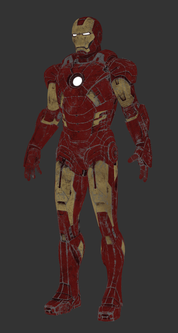
Color
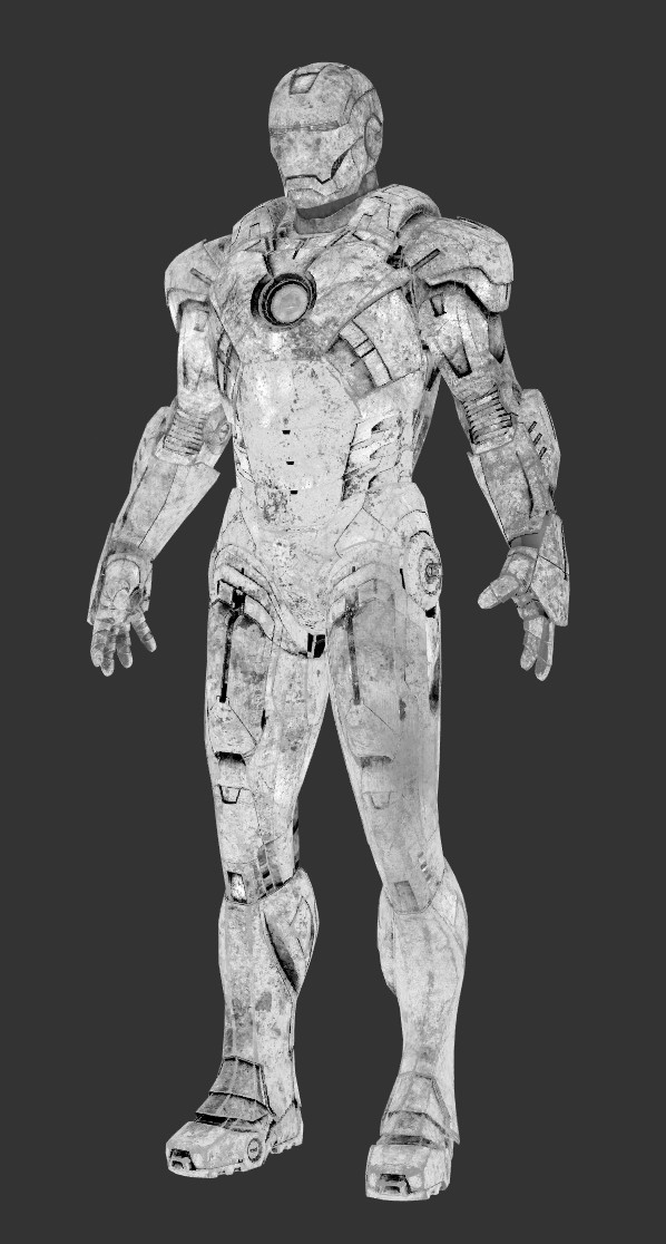
Specular
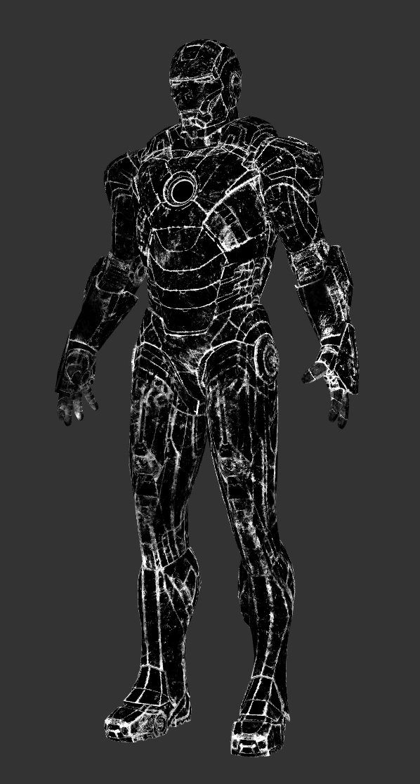
Mask 1
Color 2

Roughness

Fine displacement
Zbrush displacement in Clarisse /
This is a very quick guide to set-up Zbrush displacements in Clarisse.
As usually, the most important thing is to extract the displacement map from Zbrush correctly. To do so just check my previous post about this procedure.
Once your displacement maps are exported follow this mini tutorial.
- In order to keep everything tidy and clean I will put all the stuff related with this tutorial inside a new context called "hand".
- In this case I imported the base geometry and created a standard shader with a gray color.
- I'm just using a very simple Image Based Lighting set-up.
- Then I created a map file and a displacement node. Rename everything to keep it tidy.
- Select the displacement texture for the hand and set-up the image to raw/linear. (I'm using 32bit .exr files).
- In the displacement node set the bounding box to something like 1 to start with.
- Add the displacement map to the front value, leave the value to 1m (which is not actually 1m, its like a global unit), and set the front offset to 0.
- Finally add the displacement node to the geometry.
- That's it. Render and you will get a nice displacement.
Render with displacement map.
Render without displacement map.
- If you are still working with 16 bits displacement maps, remember to set-up the displacement node offset to 0.5 and play with the value until you find the correct behaviour.
Colour Spaces in Mari /
Mari is the standard tool these days for texturing in VFX facilities. There are so many reasons for it but one of the most important reasons is that Mari is probably the only texturing dedicated software that can handles colour spaces. In a film environment this is a very important feature because working without having control over colour profiles is pretty much like working blind.
That's why Mari and Nuke are the standard tools for texturing. We also include Zbrush as standard tool for texture artist but only for displacement maps stuff where color managment doesn't play a key role.
Right now colour management in Mari is not complete, at least is not as good as Nuke's, where you can control colour spaces for input and output sources. But Mari offers a basic colour management tools really useful for film environments. We have Mari Colour Profiles and OpenColorIO (OCIO).
As texture artists we usually work with Float Linear and 8-bit Gamma sources.
- I've loaded two different images in Mari. One of them is a Linear .exr and the other one is a Gamma2.2 .tif
- With the colour management set to none, we can check both images to see the differences between them
- We'll get same results in Nuke. Consistency is extremely important in a film pipeline.
- The first way to manage color spaces in Mari is via LUT's. Go to the color space section and choose the LUT of your project, usually provided by the cinematographer. Then change the Display Device and select your calibrated monitor. Change the Input Color Space to Linear or sRGB depending on your source material. Finally change the View Transform to your desired output like Gamma 2.2, Film, etc.
- The second method and recommended for colour management in Mari is using OCIO files. We can load these kind of files in Mari in the Color Manager window. These files are usually provided by the cinematographer or production company in general. Then just change the Display Device to your calibrated monitor, the Input Color Space to your source material and finally the View Transform to your desired output.
Turnham Green Park HDRI /
I just published another high resolution HDRI panorama for VFX.
This set includes all the original brackets, HDRI panoramas, lighting and color references for look-development and 3D lighting and an IBL setup ready to use.
Check akromatic's site for information and downloads.
Breaking a character's FACE IN MODO /
A few years ago I worked on Tim Burton's Dark Shadows at MPC. We created a full CG face for Eva Green's character Angelique.
Angelique had a fight with Johnny Depp's character Barnabas Collins, and her face and upper body gets destroyed during the action.
In that case, all the broken parts where painted by hand as texture masks, and then the FX team generated 3D geometry and simulations based on those maps, using them as guides.
Recently I had to do a similar effect, but in this particular case, the work didn't require hand painting textures for the broken pieces, just random cracks here and there.
I did some research about how to create this quickly and easily, and found out that Modo's shatter command was probably the best way to go.
This is how I achieve the effect in no time.
First of all, let's have a look to Angelique, played by Eva Green.
- Once in Modo, import the geometry. The only requirement to use this tool is that the geometry has to be closed. You can close the geometry quick and dirty, this is just to create the broken pieces, later on you can remove all the unwanted faces.
- I already painted texture maps for this character. I have a good UV layout as you can see here. This breaking tool is going to generate additional faces, adding new uv coordinates. But the existing UV's will remain as they are.
- In the setup tab you will find the Shatter&Command tool.
- Apply for example uniform type.
- There are some cool options like number of broken pieces, etc.
- Modo will create a material for all the interior pieces that are going to be generated. So cool.
- Here you can see all the broken pieces generated in no time.
- I'm going to scale down all the pieces in order to create a tiny gap between them. Now I can see them easily.
- In this particular case (as we did with Angelique) I don't need the interior faces at all. I can easily select all of them using the material that Modo generated automatically.
- Once selected all the faces just delete them.
- If I check the UVs, they seem to be perfectly fine. I can see some weird stuff that is caused by the fact that I quickly closed the mesh. But I don't worry at all about, I would never see these faces.
- I'm going to start again from scratch.
- The uniform type is very quick to generate, but all the pieces are very similar in scale.
- In this case I'm going to use the cluster type. It will generate more random pieces, creating nicer results.
- As you can see, it looks a bit better now.
- Now I'd like to generate local damage in one of the broken areas. Let's say that a bullet hits the piece and it falls apart.
- Select the fragment and apply another shatter command. In this case I'm using cluster type.
- Select all the small pieces and disable the gravity parameter under dynamics tab.
- Also set the collision set to mesh.
- I placed an sphere on top of the fragments. Then activated it's rigid body component. With the gravity force activated by default, the sphere will hit the fragments creating a nice effect.
- Play with the collision options of the fragments to get different results.
- You can see the simple but effective simulation here.
- This is a quick clay render showing the broken pieces. You can easily increase the complexity of this effect with little extra cost.
- This is the generated model, with the original UV mapping with high resolution textures applied in Mari.
- Works like a charm.
Sunny Boat HDRI panorama /
Sunny Boat HDRI equirectangular panorama.
I've been working on a new series of HDRI equirectangular panoramas for VFX.
Check the first one published on akromatic's site.