Subdivide multiple objects in Arnold by Xuan Prada

As you probably know Arnold manages subdivision individually per object. There is no way to subdivide multiple objects at once. Obviously if you have a lot of different objects in a scene going one by one adding Arnold's subdivision property doesn't sound like a good idea.

This the easiest way that I found to solve this problem and subdivide tons of objects at once.
I have no idea at all about scripting, if you have a better solution, please let me know :)

  • This is the character that I want to subdivide. As you can see it has a lot of small pieces. I'd like to keep them separate and subdivide every single one of them.

Model by SgtHK.

  • First of all, you need to select all the geometry shapes. To do this, select all the geometry objects in the outliner and paste this line in the script editor.

/* you have to select all the objects you want to subdivide, it doesn’t work with groups or locators.
once the shapes are selected just change aiSubdivType and aiSubdivIterations on the attribute spread sheet.
*/

pickWalk -d down;

string $shapesSelected[] = `ls -sl`;

  • Once all the shapes are selected go to the attribute spread editor.
  • Filter by ai subd.
  • Just type the subdivision method and iterations.
  • This is it, the whole character is now subdivided.

A bit more photogrammetry by Xuan Prada

Just a few more screenshots and renders of the last photogrammetry stuff that I've been doing. All of these are part of some training that I'll be teaching soon. Get in touch if you want to know more about it.

Rendering OpenVDB in Clarisse by Xuan Prada

Clarisse is perfectly capable of rendering volumes while maintaining it's flexible rendering options like instances or scatterers. In this particular example I'm going to render a very simple smoke simulation.

Start by creating and IBL setup. Clarisse allows you to do it with just one click.

Using a couple of matte and chrome spheres will help to establish the desired lighting situation.

To import the volume simulation just go to import -> volume.

Clarisse will show you a basic representation of the volume in the viewport. Always real time.

To improve the visual representation of the volume in viewport just click on Progressive Rendering. Lighting will also affect the volume in the viweport.

Volumes are treated pretty much like geometry in Clarisse. You can render volumes with standard shaders if you wish.

The ideal situation of course it would be using volume shaders for volume simulations.

In the material editor I'm about to use an utility -> extract property node to read any embedded property in the simulation. In this case I'm reading the temperature.

Finally I drive the temperature color with a gradient map.

If you get a lof of noise in your renders, don't forget to increase the volume sampling of your lighting sources.

Final render.

More photogrammetry stuff by Xuan Prada

I'm generating content for a photogrammetry course that I'll be teaching soon. These are just a few images of that content. More to come soon, I'll be doing a lot of examples and exercises using photogrammetry for visual effects projects.

rendering Maya particles in Clarisse by Xuan Prada

This is a very simple tutorial explaining how to render particle systems simulated in Maya inside Isotropix Clarisse. I already have a few posts about using Clarisse for different purposes, if you check by the tag "Clarisse" you will find all the previous posts. Hope to be publishing more soon.

In this particular case we'll be using a very simple particle system in Maya. We are going to export it to Clarisse and use custom geometries and Clarisse's powerful scatterer system to render millions of polygons very fast and nicely.

  • Once your particle system has been simulated in Maya, export it via Alembic. One of the standard 3D formats for exchanging information in VFX.
  • Create an IBL rig in Clarisse. In a previous post I explain how to do it, it is quite simple.
  • With Clarisse 2.0 it is so simple to do, just one click and you are ready to go.
  • Go to File -> Import -> Scene and select the Alembic file exported from Maya.
  • It comes with 2 types of particles, a grid acting as ground and the render camera.
  • Create a few contexts to keep everything tidy. Geo, particles, cameras and materials.
  • In the geo context I imported the toy_man and the toy_truck models (.obj) and moved the grid from the main context to the geo context.
  • Moved the 2 particles systems and the camera to their correspondent contexts.
  • In the materials context I created 2 materials and 2 color textures for the models. Very simple shaders and textures.
  • In the particles context I created a new scatterer calle scatterer_typeA.
  • In the geometry support of the scatter add the particles_typeA and in the geometry section add the toy_man model.
  • I’m also adding some variation to the rotation.
  • If I move my timeline I will see the particle animation using the toy_man model.
  • Do not forget to assign the material created before.
  • Create another scatterer for the partycles_typeB and configure the geometry support and the geometry to be used.
  • Add also some rotation and position variation.
  • As these models are quite big compared with the toy figurine, I’m offsetting the particle effect to reduce the presence of toy_trucks in the scene.
  • Before rendering, I’d like to add some motion blur to the scene. Go to raytracer -> Motion Blur -> 3D motion blur. Now you are ready to render the whole animation.

Shipping 3/8 adaptors by Xuan Prada

On behalf of akromatic.

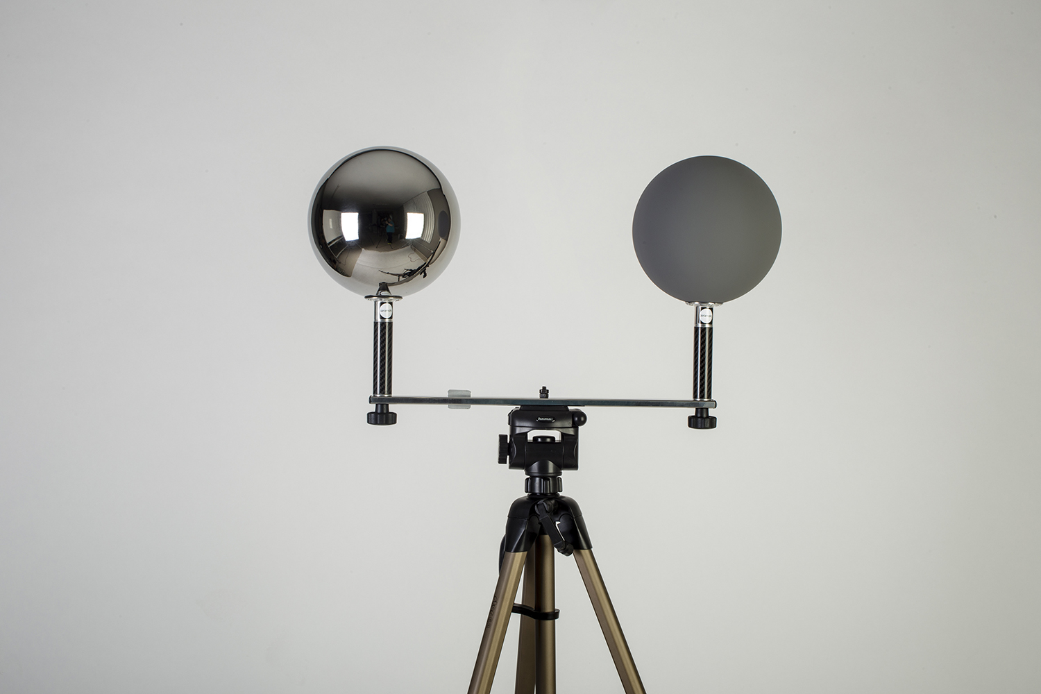
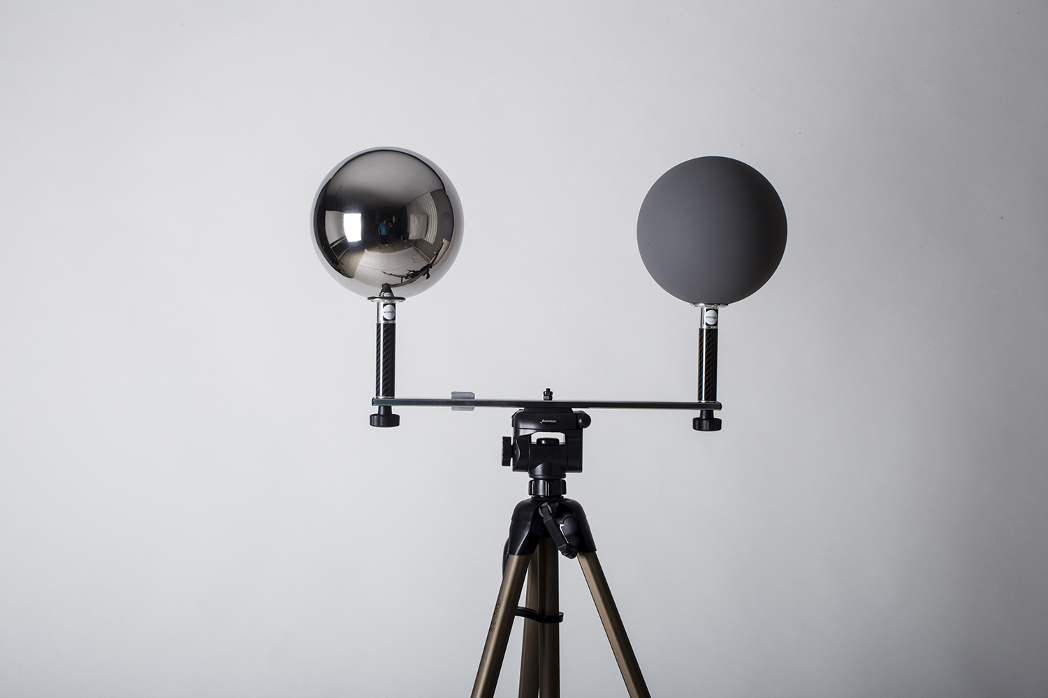
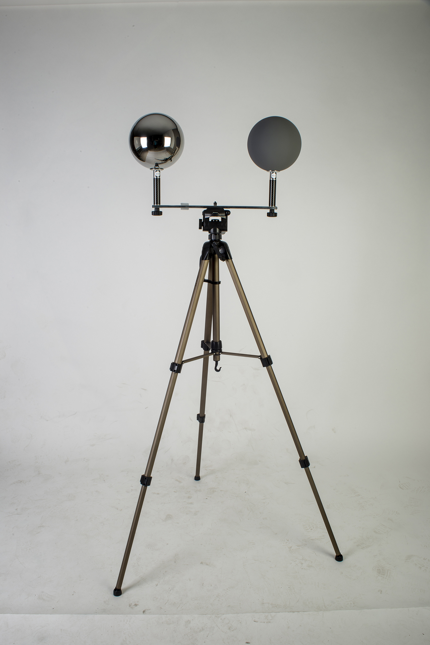
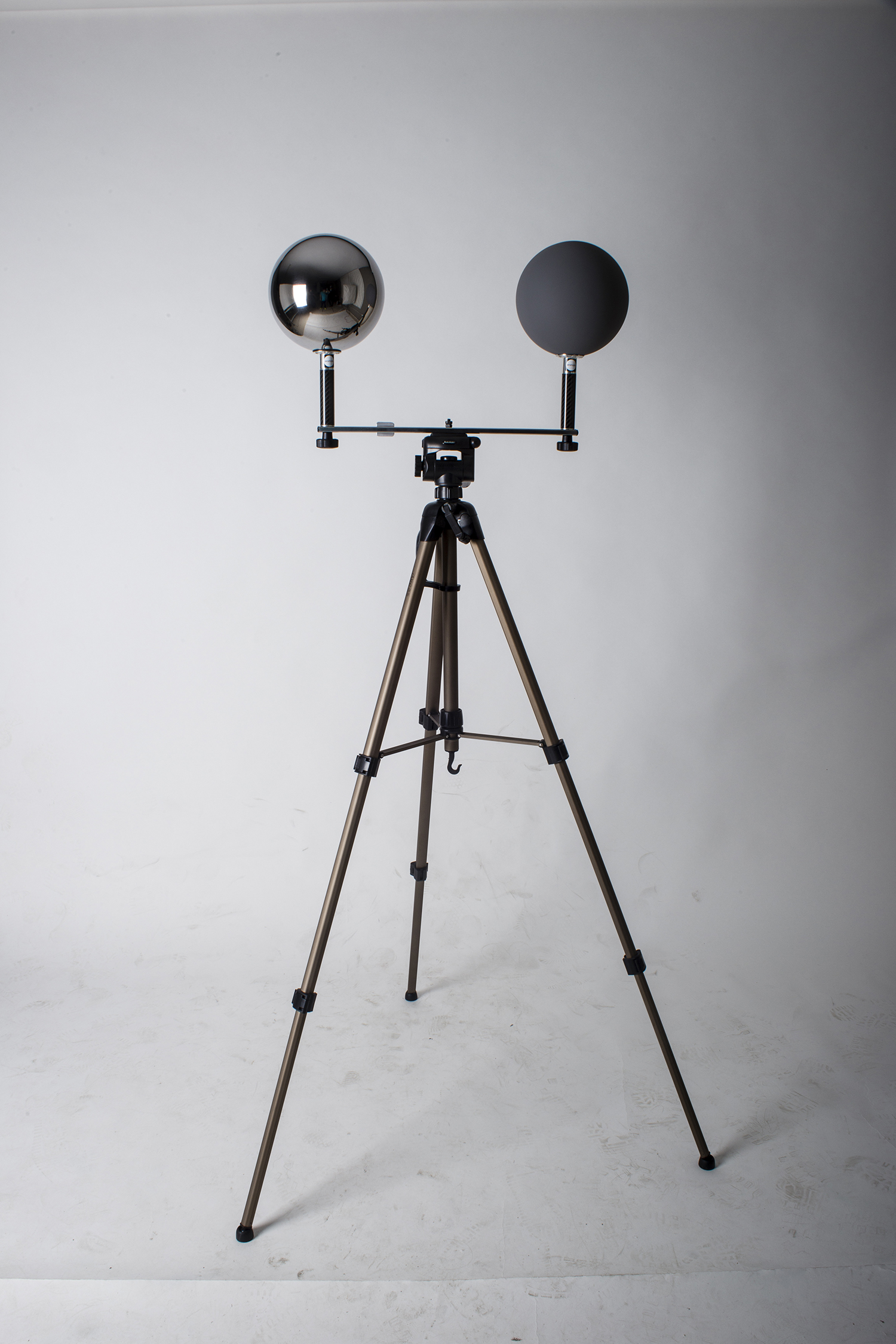
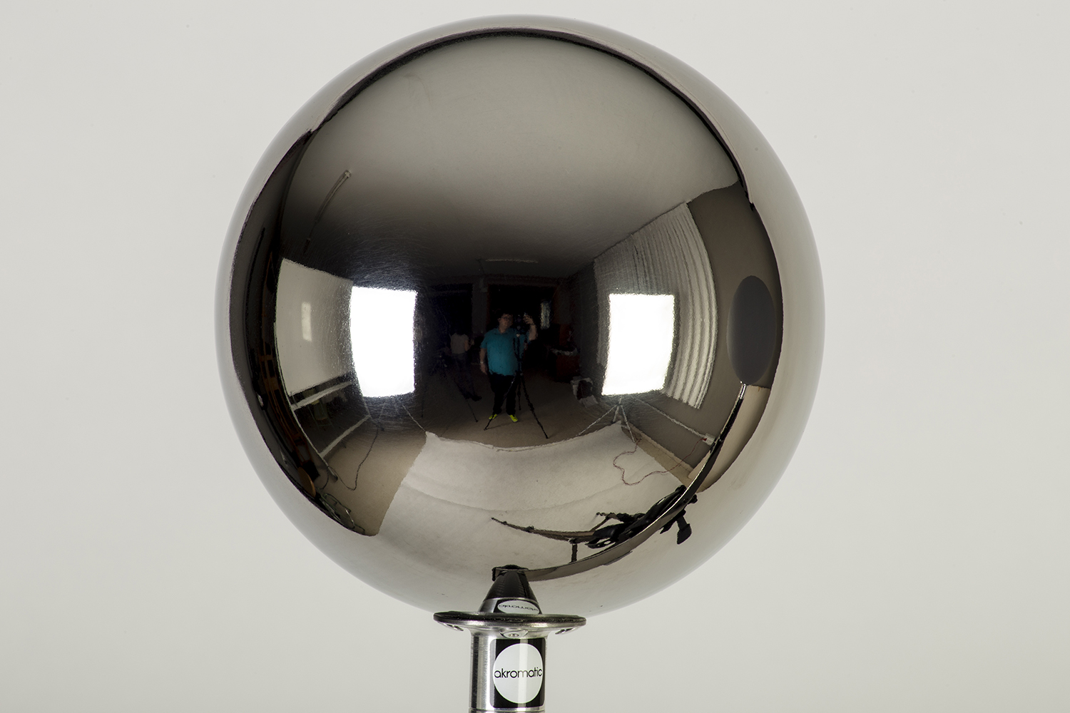
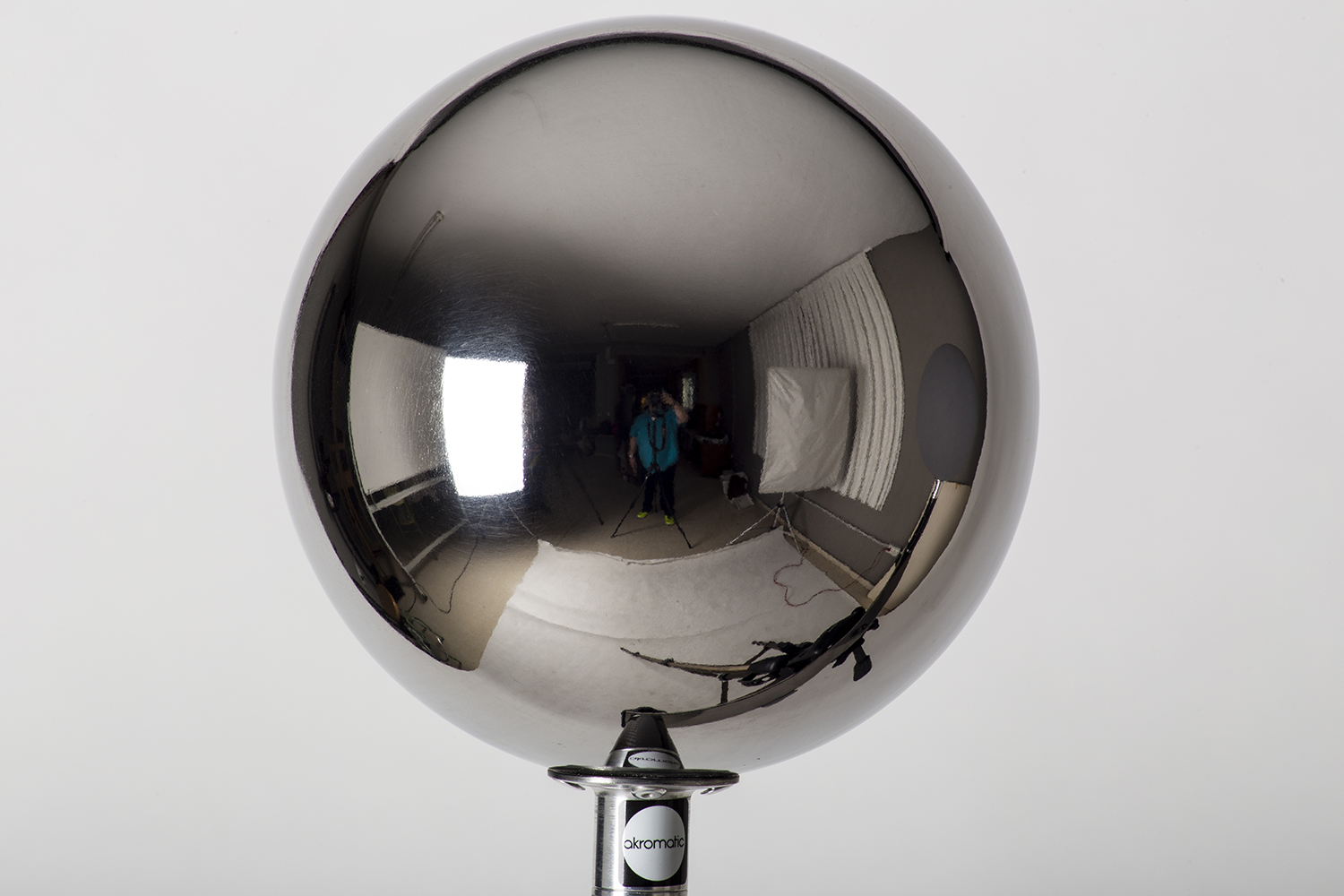
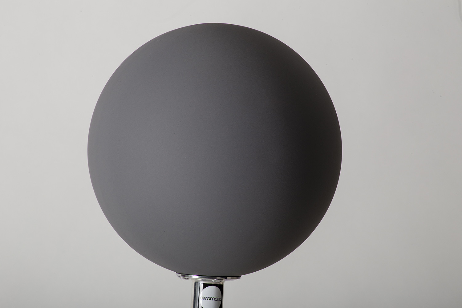
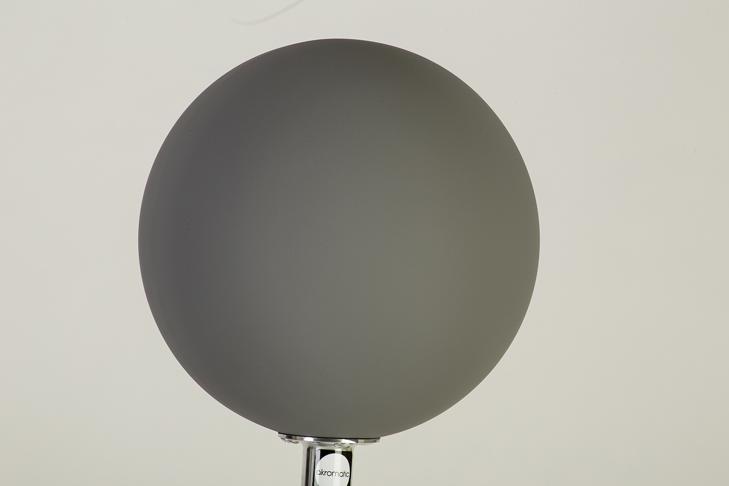
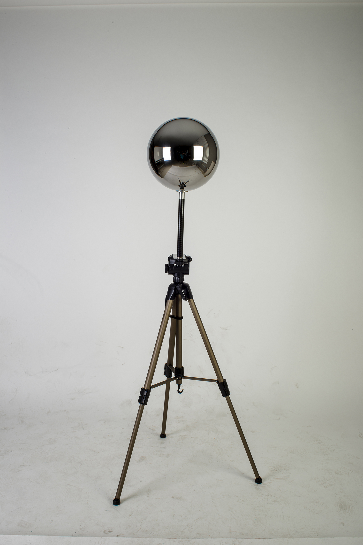
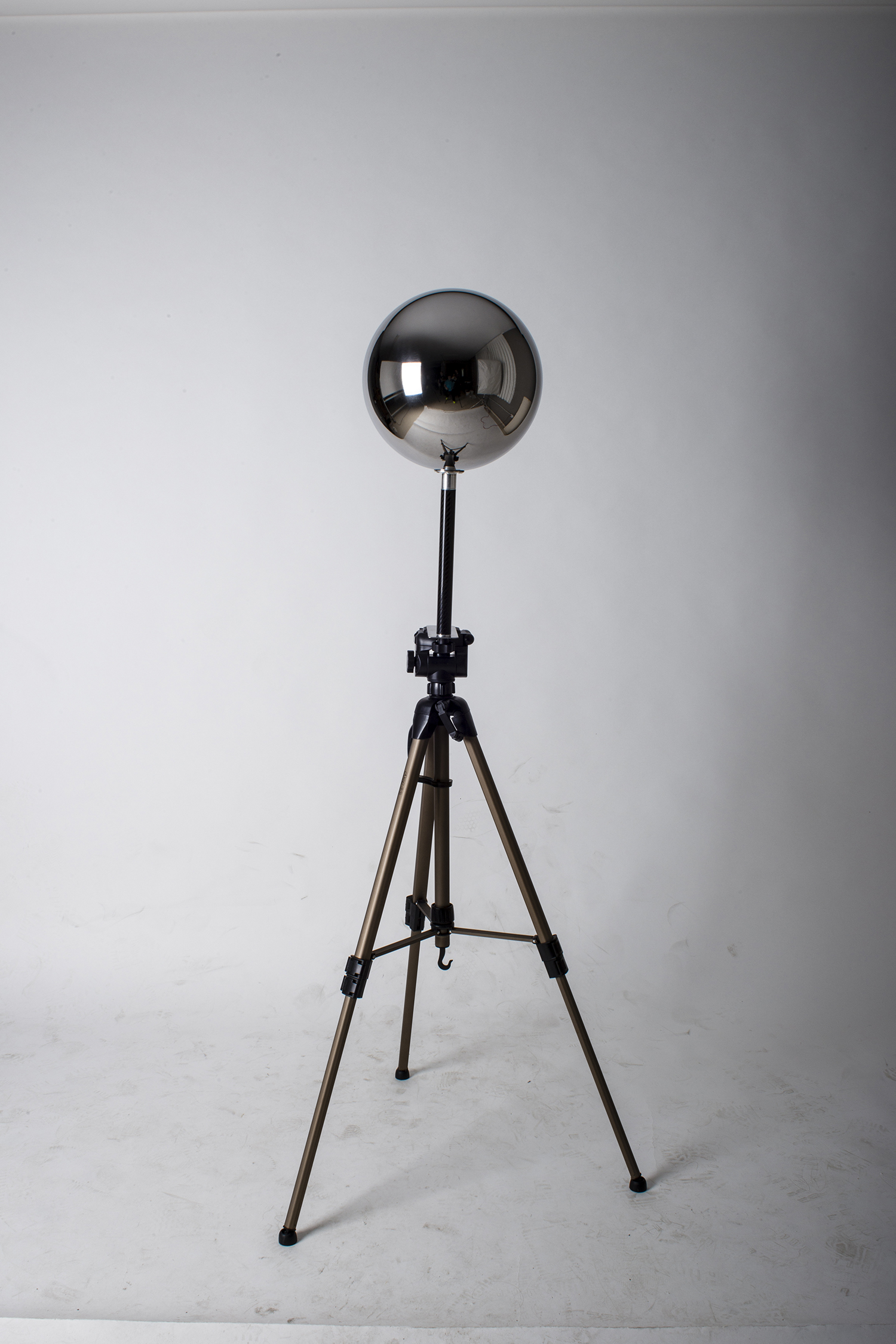
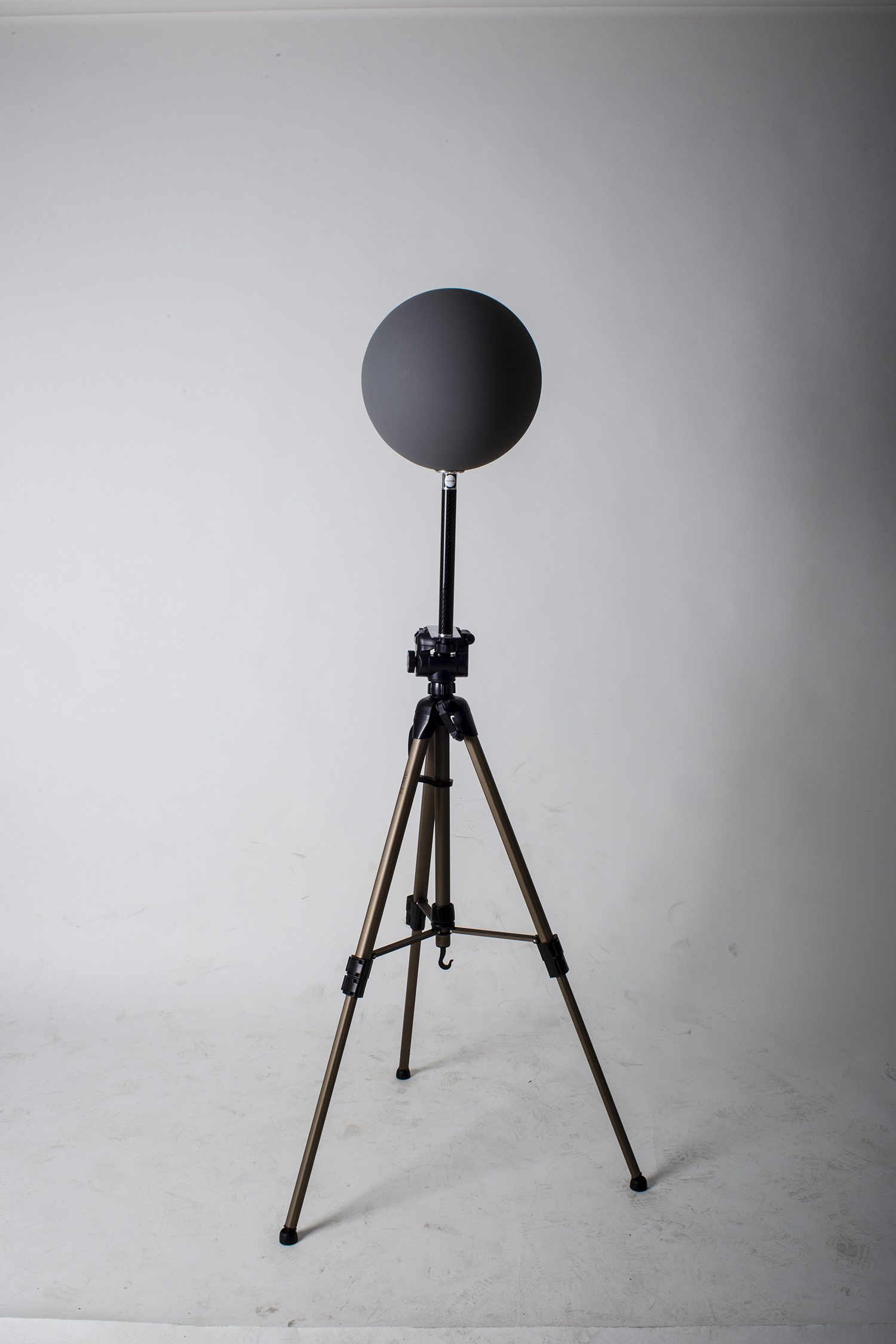
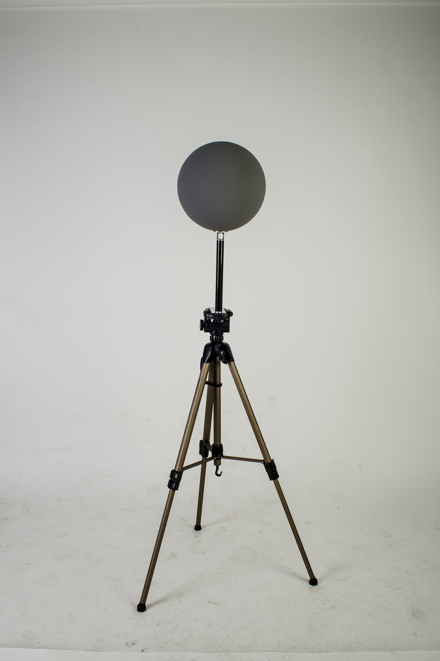
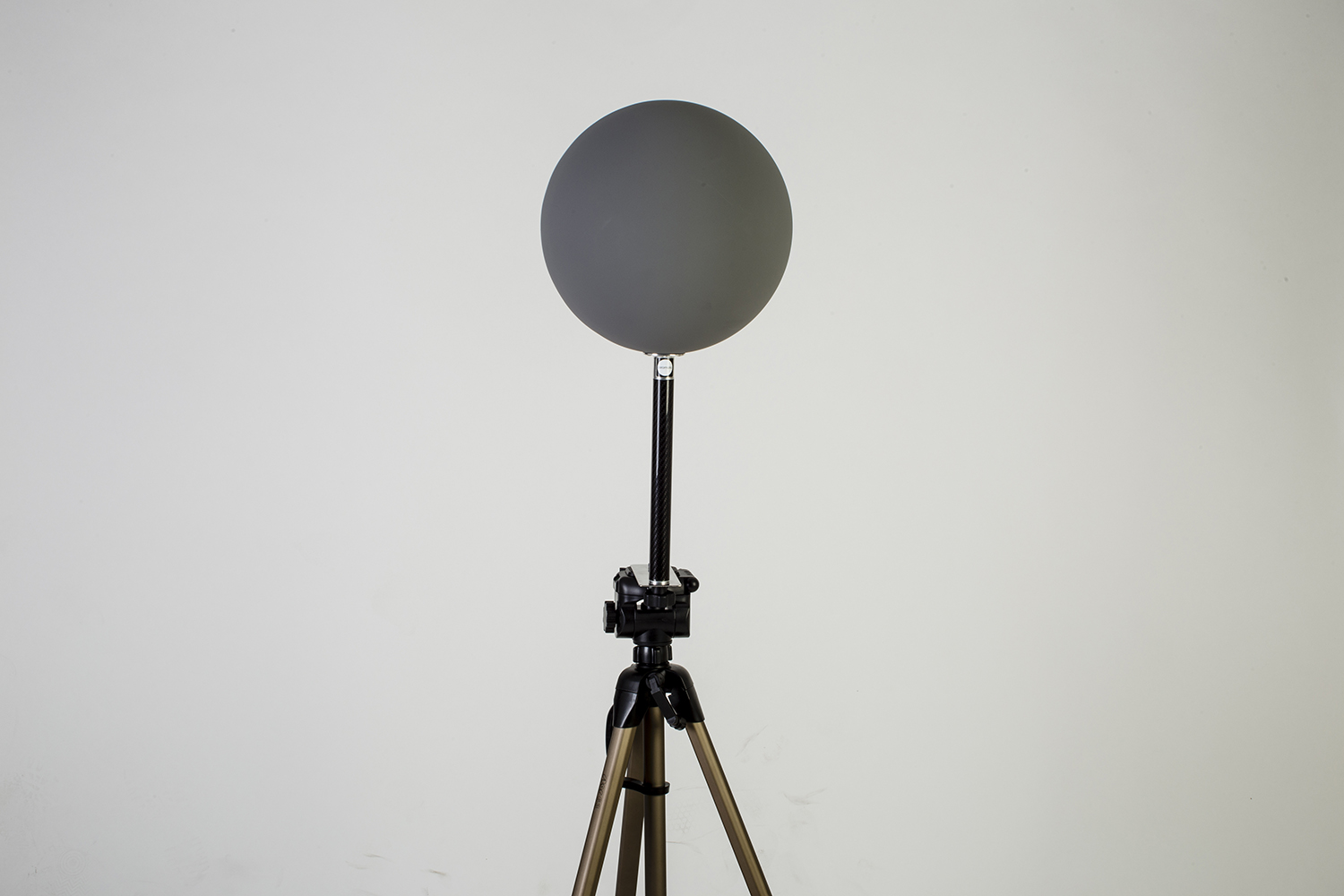
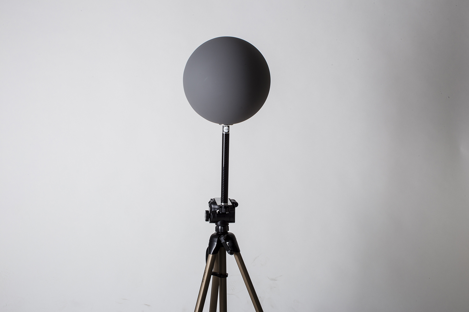
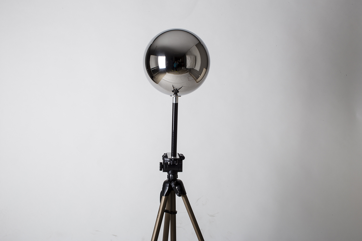
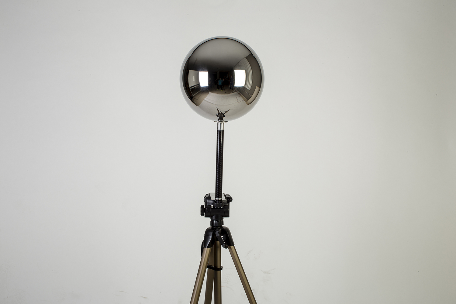
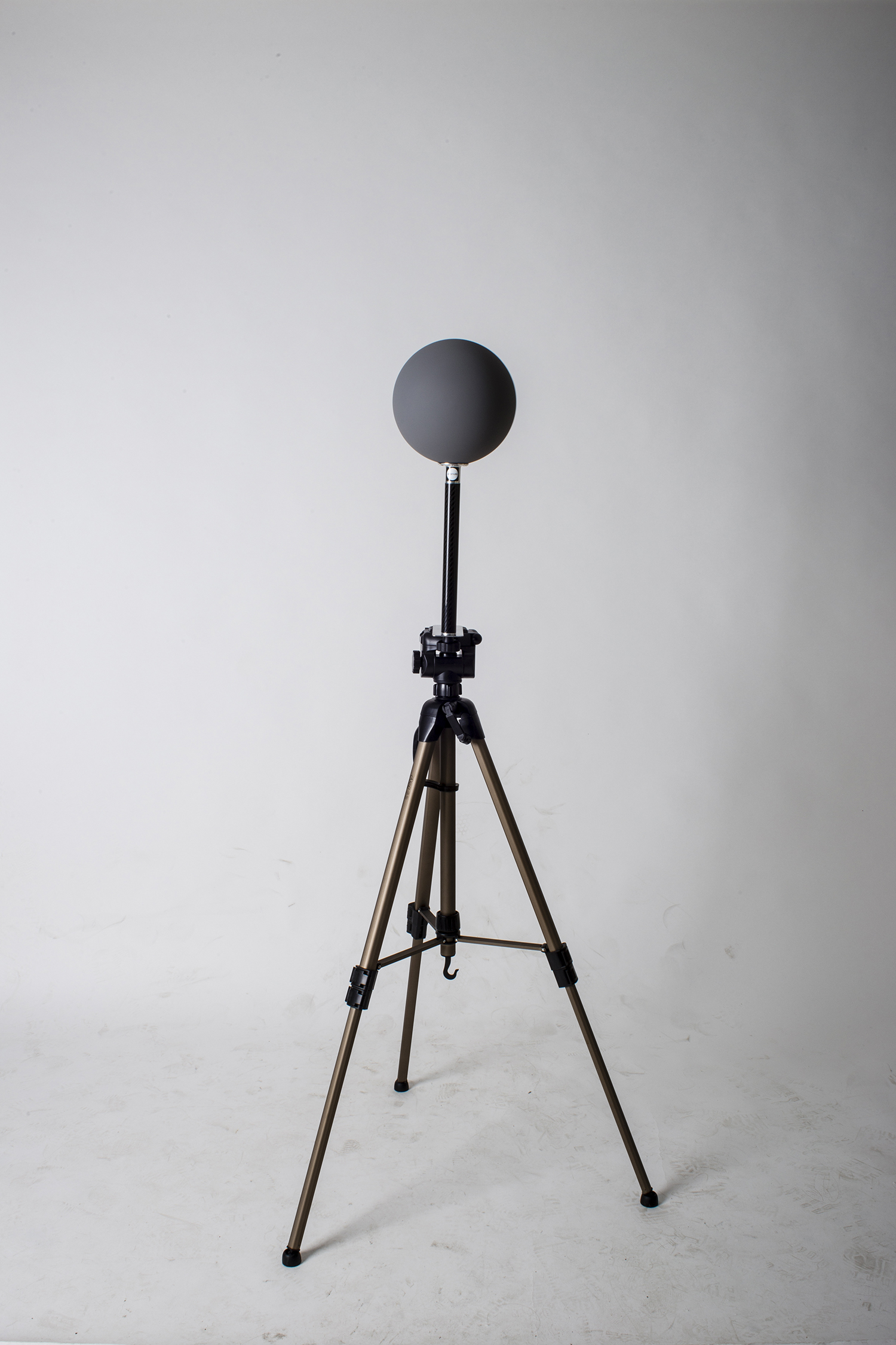
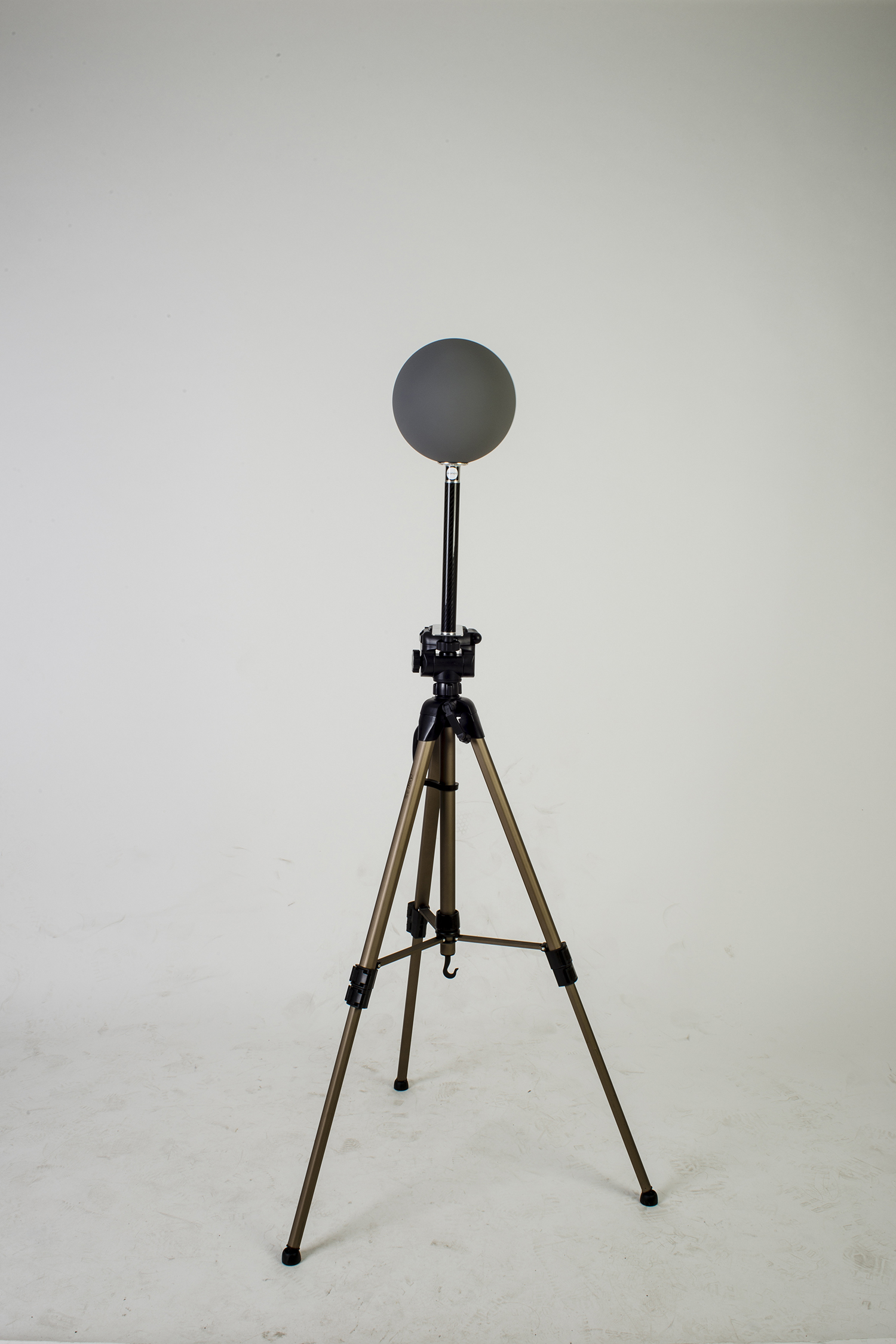
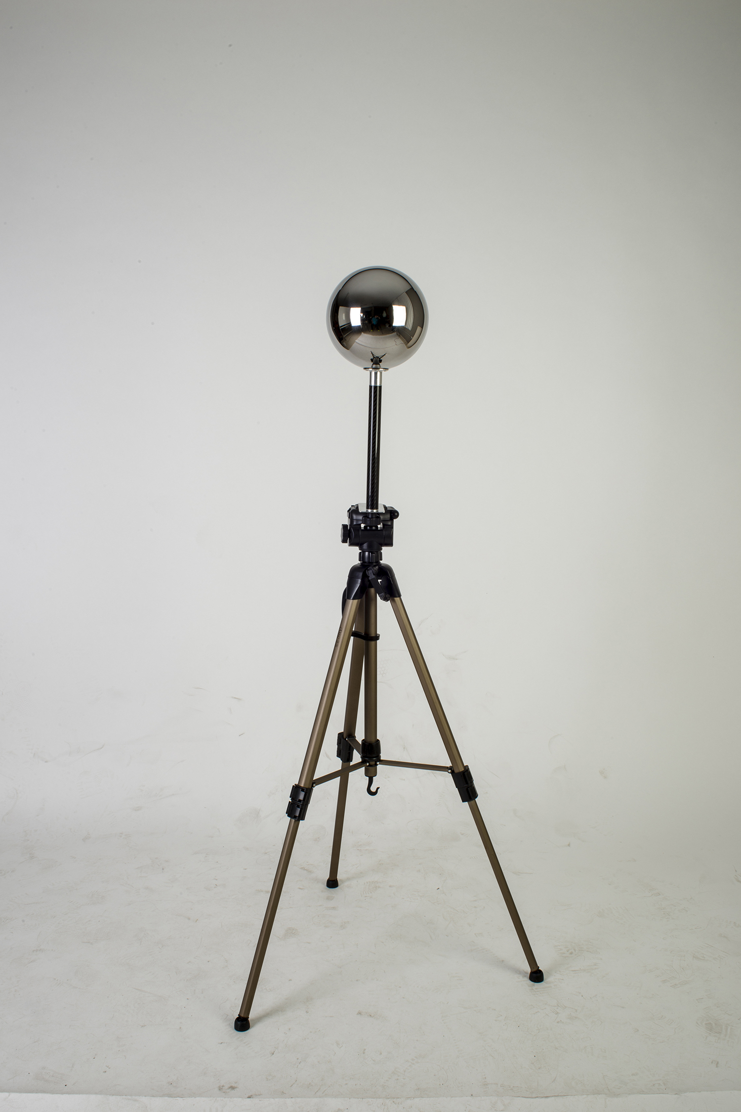
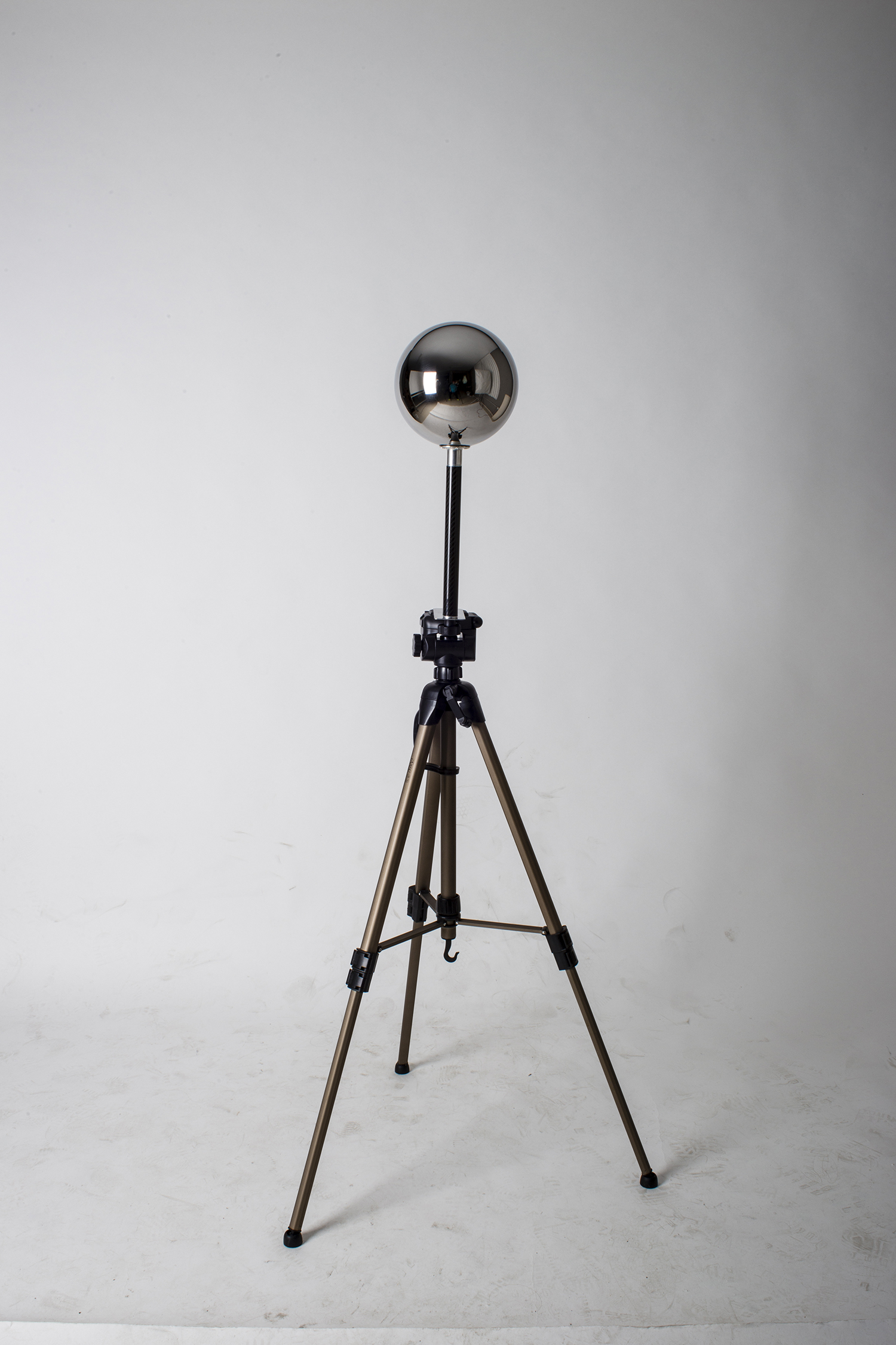
We are shipping our new 3/8 adaptors that can fit all of our Lighting Checker handles. This is the best way to attach any of our Lighting Checkers individually to any standard 3/8 professional tripod.

This adaptor is included when purchasing Lighting Checker "Mono" from our online store.
If you need to buy additional adaptors for other kits or other purposes, you can buy them as well in our store.

These 3/8 adaptors are made of high quality aluminium.

Akromatic 3/8 adaptors by Xuan Prada

In order to improve our custom plate solutions to attach akromatic spheres on your tripod, we came out with the akromatic adaptor, which will allow you to attach all of our spheres and carbon fibre handles to any tripod with standard 3/8 attachment.

We'll be sending this adaptor with our akromatic kits very soon.
See it in action.
Visit akromatic.com for more information about this product.

Meshlab align to ground by Xuan Prada

If you deal a lot with 3D scans, Lidars, photogrammetry and other heavy models, you probably use Meshlab. This "little" software is great managing 75 million polygon Lidars and other complex meshes. Photoscan experienced users usually play with the align to ground tool to establish the correct axis for their resulting meshes.

If you look for this option in Meshlab you wouldn't find it, at least I didn't. Please let me know if you know how to do this.
What I found is a clever workaround to do the same same thing with a couple of clicks.

  • Import your Lidar or photogrammetry, and also import a ground plane exported from Maya. This is going to be your floor, ground or base axis.
  • This is a very simple example. The goal is to align the sneaker to the ground. I would like to deal with such a simple lidars at work :)
  • Click on the align icon.
  • In the align tool window, select the ground object and click on glue here mesh.
  • Notice the star that appears before the name of the object indicating that the mesh has been selected as base.
  • Select the lidar, photogrammetry or whatever geometry that need to be aligned and click on point based glueing.
  • In this little windows you can see both objects. Feel free to navigate around it behaves like a normal viewport.
  • Select one point at the base of the lidar by double clicking on top of it. Then do the same in one point of the base geo.
  • Repeat the same process. You'll need at least 4 points.
  • Done :)

Dealing with Ptex displacement by Xuan Prada

Render using Ptex displacement.

What if you are working with Ptex but need to do some kind of Zbrush displacement work?
How can you render that?

As you probably now, Zbrush doesn't support Ptex. I'm not a super fan of Ptex (but I will be soon) but sometimes I do not have time or simply I don't want to make proper UV mapping. Then, if Zbrush doesn't export Ptex and my assets don't have any sort of UV coordinates, can't I use Ptex at all for my displacement information?

Yes, you can use Ptex.

Base geometry render. No displacement.

  • In this image below, I have a detailed 3D scan which has been processed in Meshlab to reduce the crazy amount of polygons.
  • Now I have imported the model via obj in Zbrush. Only 500.000 polys but it looks great though.
  • We are going to be using Zbrush to create a very quick retopology for this demo. We could use Maya or Modo to create a production ready model.
  • Using the Zremesher tool which is great for some type of retopology tasks, we get this low res model. Good enough for our purpose here.
  • Next step would be exporting both model, high and low resolution as .obj
  • We are going to use these models in Mudbox to create our Ptex based displacement. Yes, Mudbox does support Ptex.
  • Once imported keep both of them visible.
  • Export displacement maps. Have a look in the image below at the options you need to tweak.
  • Basically you need to activate Ptex displacement, 32bits, the texel resolution, etc)
  • And that's it. You should be able to render your Zbrush details using Ptex now.

Clarisse AOVs overview by Xuan Prada

This is a very quick overview of how to use AOVs in Clarisse.

  • I started from this very simple scene.

  • Select your render image and then the 3D layer.

  • Open the AOV editor and select the components that you need for your compositing. In my case I only need diffuse, reflection and sss.

  • Click on the plus button to enable them.

  • Now you can check every single AOV in the image view frame buffer.

  • Create a new context called "compositing" and inside of it create a new image called "comp_image".

  • Add a black color layer.

  • Add an add filter and texture it using a constant color. This will be the entry point for our comp.

  • Drag and drop the constant color to the material editor.

  • Drag and drop the image render to the material editor.

  • If you connect the image render to the the constant color input, you will see the beauty pass. Let's split it into AOVs.

  • Rename the map to diffuse and select the diffuse channel.

  • Repeat the process with all the AOVs, you can copy and paste the map node.

  • Add a few add nodes to merge all the AOVs until you get the beauty pass. This is it, your comp in a real time 3D environment. Whatever you change/add in you scene will be updated automatically.

  • Lets say that you don't need your comp inside Clarisse. Fine, just select your render image, configure the output and bring the render manager to output your final render.

  • Just do the comp in Nuke as usual.

Combining Zbrush and Mari displacement maps by Xuan Prada

Short and sweet (hopefully).
It seems to be quite a normal topic these days. Mari and Zbrush are commonly used by texture artists. Combining displacement maps in look-dev is a must.

I'll be using Maya and Arnold for this demo but any 3D software and renderer is welcome to use the same workflow.

  • Using Zbrush displacements is no brainer. Just export them as 32 bit .exr and that's it. Set your render subdivisions in Arnold and leave the default settings for displacement. Zero value is always 0 and height should be 1 to match your Zbrush sculpt.
  • These are the maps that I'm using. First the Zbrush map and below the Mari map.
  • No displacement at all in this render. This is just the base geometry.
  • In this render I'm only using the Zbrush displacement.
  • In order to combine Zbrush displacement maps and Mari displacement maps you need to normalise the ranges. If you use the same range your Mari displacement would be huge compared with the Zbrush one.
  • Using a multiply node is so easy to control the strength of the Mari displacement. Connect the map to the input1 and play with the values in the input2.
  • To mix both displacement maps you can use an average node. Connect the Zbrush map to the input0 and the Mari map (multiply node) to the input1.
  • The average node can't be connected straight o the displacement node. Use ramp node with the average node connected to it's color and then connect the ramp to the displacement default input.
  • In this render I'm combining both, Zbrush map and Mari map.
  • In this other example I'm about to combine two displacements using a mask. I'll be using a Zbrush displacement as general displacement, and then I'm going to use a mask painted in Mari to reveal another displacement painted in Mari as well.
  • As mask I'm going to use the same symbol that I used before as displacement 2.
  • And as new displacement I'm going to use a procedural map painted in Mari.
  • The first thing to do is exactly the same operation that we did before. Control the strength of the Mari's displacement using a multiply node.
  • Then use another multiply node with the Mari's map (multiply) connected to it's input1 and the mask connected to it's input2. This will reveal the Mari's displacement only in the white areas of the mask.
  • And the rest is exactly the same as we did before. Connect the Zbrush displacement to the input0 of the average node and the Mari's displacement (multiply) to the input1 of the average node. Then the average node to the ramp's color and the ramp to the displacement default input.
  • This is the final render.