On behalf of akromatic.
We are shipping our new 3/8 adaptors that can fit all of our Lighting Checker handles. This is the best way to attach any of our Lighting Checkers individually to any standard 3/8 professional tripod.
This adaptor is included when purchasing Lighting Checker "Mono" from our online store.
If you need to buy additional adaptors for other kits or other purposes, you can buy them as well in our store.
These 3/8 adaptors are made of high quality aluminium.
Photogrammetry tests /
I've been doing a lot of photogrammetry stuff recently, can't show much yet but I will soon.
These are just a few tests that I did to get comfortable scanning small props.
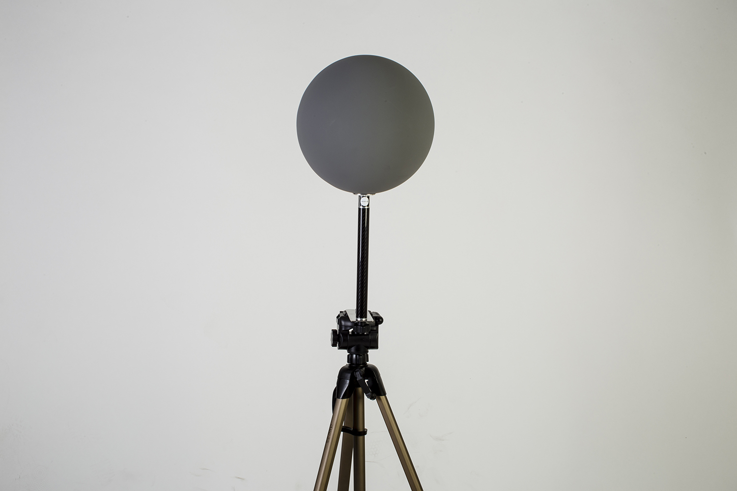
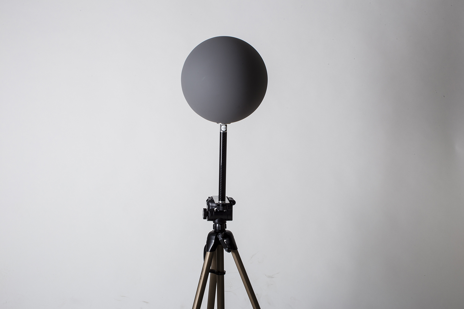
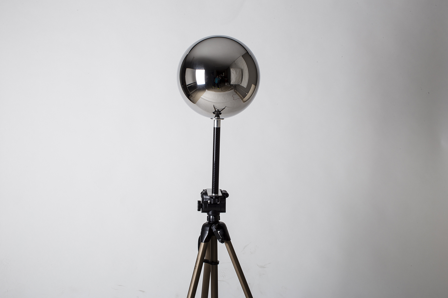
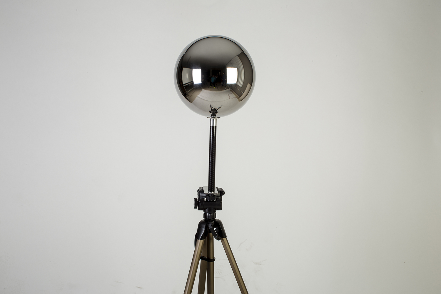
Akromatic 3/8 adaptors /
In order to improve our custom plate solutions to attach akromatic spheres on your tripod, we came out with the akromatic adaptor, which will allow you to attach all of our spheres and carbon fibre handles to any tripod with standard 3/8 attachment.
We'll be sending this adaptor with our akromatic kits very soon.
See it in action.
Visit akromatic.com for more information about this product.
Meshlab align to ground /
If you deal a lot with 3D scans, Lidars, photogrammetry and other heavy models, you probably use Meshlab. This "little" software is great managing 75 million polygon Lidars and other complex meshes. Photoscan experienced users usually play with the align to ground tool to establish the correct axis for their resulting meshes.
If you look for this option in Meshlab you wouldn't find it, at least I didn't. Please let me know if you know how to do this.
What I found is a clever workaround to do the same same thing with a couple of clicks.
- Import your Lidar or photogrammetry, and also import a ground plane exported from Maya. This is going to be your floor, ground or base axis.
- This is a very simple example. The goal is to align the sneaker to the ground. I would like to deal with such a simple lidars at work :)
- Click on the align icon.
- In the align tool window, select the ground object and click on glue here mesh.
- Notice the star that appears before the name of the object indicating that the mesh has been selected as base.
- Select the lidar, photogrammetry or whatever geometry that need to be aligned and click on point based glueing.
- In this little windows you can see both objects. Feel free to navigate around it behaves like a normal viewport.
- Select one point at the base of the lidar by double clicking on top of it. Then do the same in one point of the base geo.
- Repeat the same process. You'll need at least 4 points.
- Done :)
Dealing with Ptex displacement /
Render using Ptex displacement.
What if you are working with Ptex but need to do some kind of Zbrush displacement work?
How can you render that?
As you probably now, Zbrush doesn't support Ptex. I'm not a super fan of Ptex (but I will be soon) but sometimes I do not have time or simply I don't want to make proper UV mapping. Then, if Zbrush doesn't export Ptex and my assets don't have any sort of UV coordinates, can't I use Ptex at all for my displacement information?
Yes, you can use Ptex.
Base geometry render. No displacement.
- In this image below, I have a detailed 3D scan which has been processed in Meshlab to reduce the crazy amount of polygons.
- Now I have imported the model via obj in Zbrush. Only 500.000 polys but it looks great though.
- We are going to be using Zbrush to create a very quick retopology for this demo. We could use Maya or Modo to create a production ready model.
- Using the Zremesher tool which is great for some type of retopology tasks, we get this low res model. Good enough for our purpose here.
- Next step would be exporting both model, high and low resolution as .obj
- We are going to use these models in Mudbox to create our Ptex based displacement. Yes, Mudbox does support Ptex.
- Once imported keep both of them visible.
- Export displacement maps. Have a look in the image below at the options you need to tweak.
- Basically you need to activate Ptex displacement, 32bits, the texel resolution, etc)
- To setup your displacement setup in Maya and Vray just follow the 32 bits displacement rule.
- And that's it. You should be able to render your Zbrush details using Ptex now.
mmColorTarget /
This is a very quick demo of how to install on Mac and use the gizmo mmColorTarget or at least how I use it for my texturing/references and lighting process. The gizmo itself was created by Marco Meyer.
Akromatic mini base available /
The "akromatic mini base" is already available here. Shipping worldwide as usual.
Clarisse AOVs overview /
This is a very quick overview of how to use AOVs in Clarisse.
I started from this very simple scene.
Select your render image and then the 3D layer.
Open the AOV editor and select the components that you need for your compositing. In my case I only need diffuse, reflection and sss.
Click on the plus button to enable them.
Now you can check every single AOV in the image view frame buffer.
Create a new context called "compositing" and inside of it create a new image called "comp_image".
Add a black color layer.
Add an add filter and texture it using a constant color. This will be the entry point for our comp.
Drag and drop the constant color to the material editor.
Drag and drop the image render to the material editor.
If you connect the image render to the the constant color input, you will see the beauty pass. Let's split it into AOVs.
Rename the map to diffuse and select the diffuse channel.
Repeat the process with all the AOVs, you can copy and paste the map node.
Add a few add nodes to merge all the AOVs until you get the beauty pass. This is it, your comp in a real time 3D environment. Whatever you change/add in you scene will be updated automatically.
Lets say that you don't need your comp inside Clarisse. Fine, just select your render image, configure the output and bring the render manager to output your final render.
- Just do the comp in Nuke as usual.
Combining Zbrush displacement and Mari displacement /
I recorded this video while ago for another website, it's in Spanish but you won't have any problem to follow the instructions just watching the video.
Two final shots for this robot fella /
Two quick shots that I did for this character.
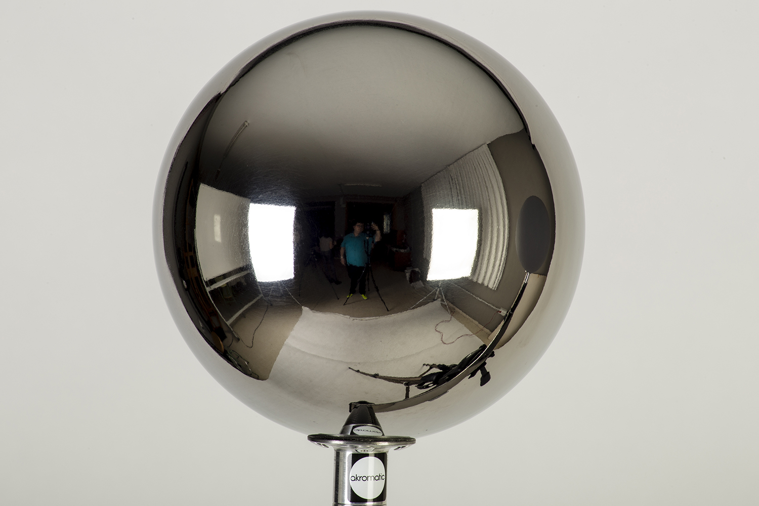
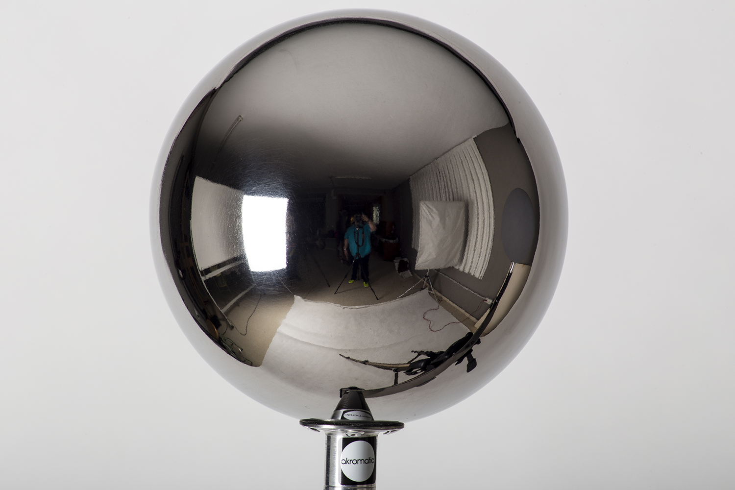
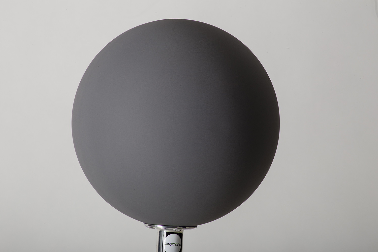
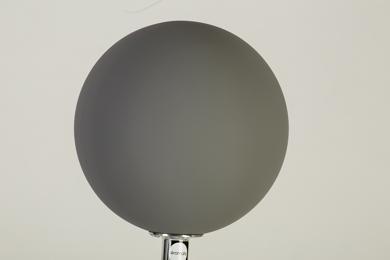
Akromatic pictures from the studio /
Just a few images of our Akromatic productos during a look-development session for VFX.
Robot shot 01 /
This is a work in progress image.
More shots on their way.
Robot /
Just for fun :)
Combining Zbrush and Mari displacement maps /
Short and sweet (hopefully).
It seems to be quite a normal topic these days. Mari and Zbrush are commonly used by texture artists. Combining displacement maps in look-dev is a must.
I'll be using Maya and Arnold for this demo but any 3D software and renderer is welcome to use the same workflow.
- Using Zbrush displacements is no brainer. Just export them as 32 bit .exr and that's it. Set your render subdivisions in Arnold and leave the default settings for displacement. Zero value is always 0 and height should be 1 to match your Zbrush sculpt.
- These are the maps that I'm using. First the Zbrush map and below the Mari map.
- No displacement at all in this render. This is just the base geometry.
- In this render I'm only using the Zbrush displacement.
- In order to combine Zbrush displacement maps and Mari displacement maps you need to normalise the ranges. If you use the same range your Mari displacement would be huge compared with the Zbrush one.
- Using a multiply node is so easy to control the strength of the Mari displacement. Connect the map to the input1 and play with the values in the input2.
- To mix both displacement maps you can use an average node. Connect the Zbrush map to the input0 and the Mari map (multiply node) to the input1.
- The average node can't be connected straight o the displacement node. Use ramp node with the average node connected to it's color and then connect the ramp to the displacement default input.
- In this render I'm combining both, Zbrush map and Mari map.
- In this other example I'm about to combine two displacements using a mask. I'll be using a Zbrush displacement as general displacement, and then I'm going to use a mask painted in Mari to reveal another displacement painted in Mari as well.
- As mask I'm going to use the same symbol that I used before as displacement 2.
- And as new displacement I'm going to use a procedural map painted in Mari.
- The first thing to do is exactly the same operation that we did before. Control the strength of the Mari's displacement using a multiply node.
- Then use another multiply node with the Mari's map (multiply) connected to it's input1 and the mask connected to it's input2. This will reveal the Mari's displacement only in the white areas of the mask.
- And the rest is exactly the same as we did before. Connect the Zbrush displacement to the input0 of the average node and the Mari's displacement (multiply) to the input1 of the average node. Then the average node to the ramp's color and the ramp to the displacement default input.
- This is the final render.
Mission ImposSible 5 trailer 2 /
This is the new trailer for Mission Impossible 5. I've been working on this over the last few months.
Great job by our Double Negative's team.
Ellenborough Park Sunrise /
I shot a new HDRI panorama for 3D Lighting and Look-development for akromatic.com
Check it out here, it's free!
Texturing and look-dev at TD-U /
Third call for my texturing and look-development course at TD-U.
It is an 8 week workshop starting at May 25th to July 20th, 2015.
All the info here.
RGB masks /
We use RGB masks all the time in VFX, don't we?
They are very handy and we can save a lot of extra texture maps combining 4 channels in one single texture map RGB+A.
We use them to mix shaders in look-dev stage, or as IDs for compositing, or maybe as utility passes for things like motion blur o depth.
Let's see how I use RGB masks in my common software: Maya, Clarisse, Mari and Nuke.
Maya
- I use a surface shader with a layered texture connected.
- I connect all the shaders that I need to mix to the layered texture.
- Then I use a remapColor node with the RGB mask connected as mask for each one of the shaders.
This is the RGB mask that I'm using.
- We need to indicate which RGB channel we want to use in each remapColor node.
- Then just use the output as mask for the shaders.
Clarisse
- In Clarisse I use a reorder node connected to my RGB mask.
- Just indicate the desired channel in the channel order parameter.
- To convert the RGB channel to alpha just type it in the channel order field.
Mari
- You will only need a shuffle adjustment layer and select the required channel.
Nuke
- You can use a shuffle node and select the channel.
- Or maybe a keyer node and select the channel in the operation parameter. (this will place the channel only in the alpha).
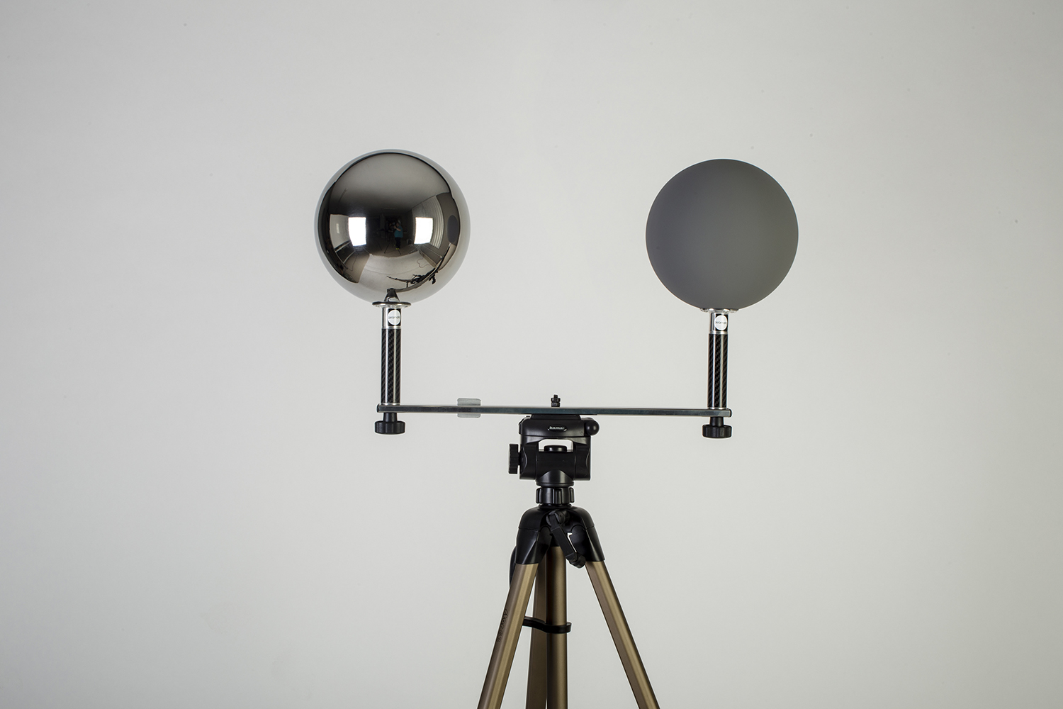
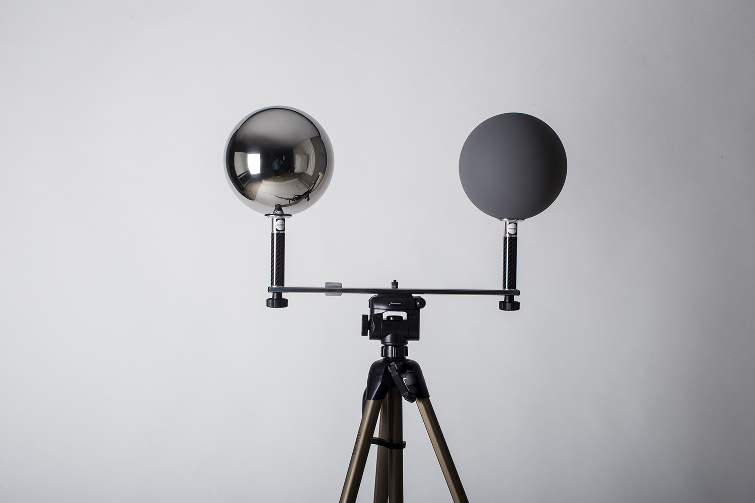
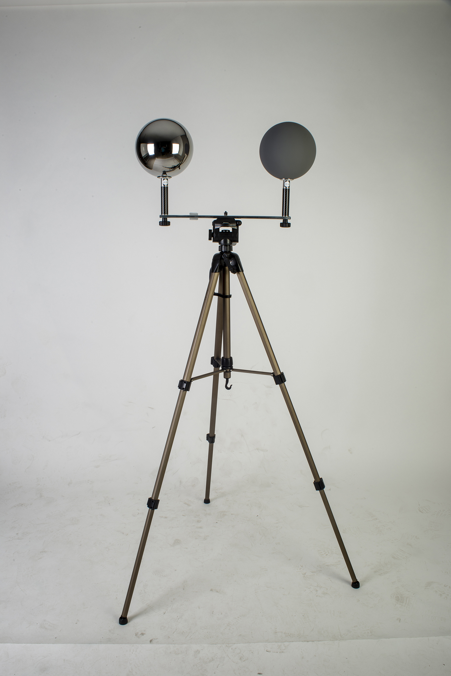
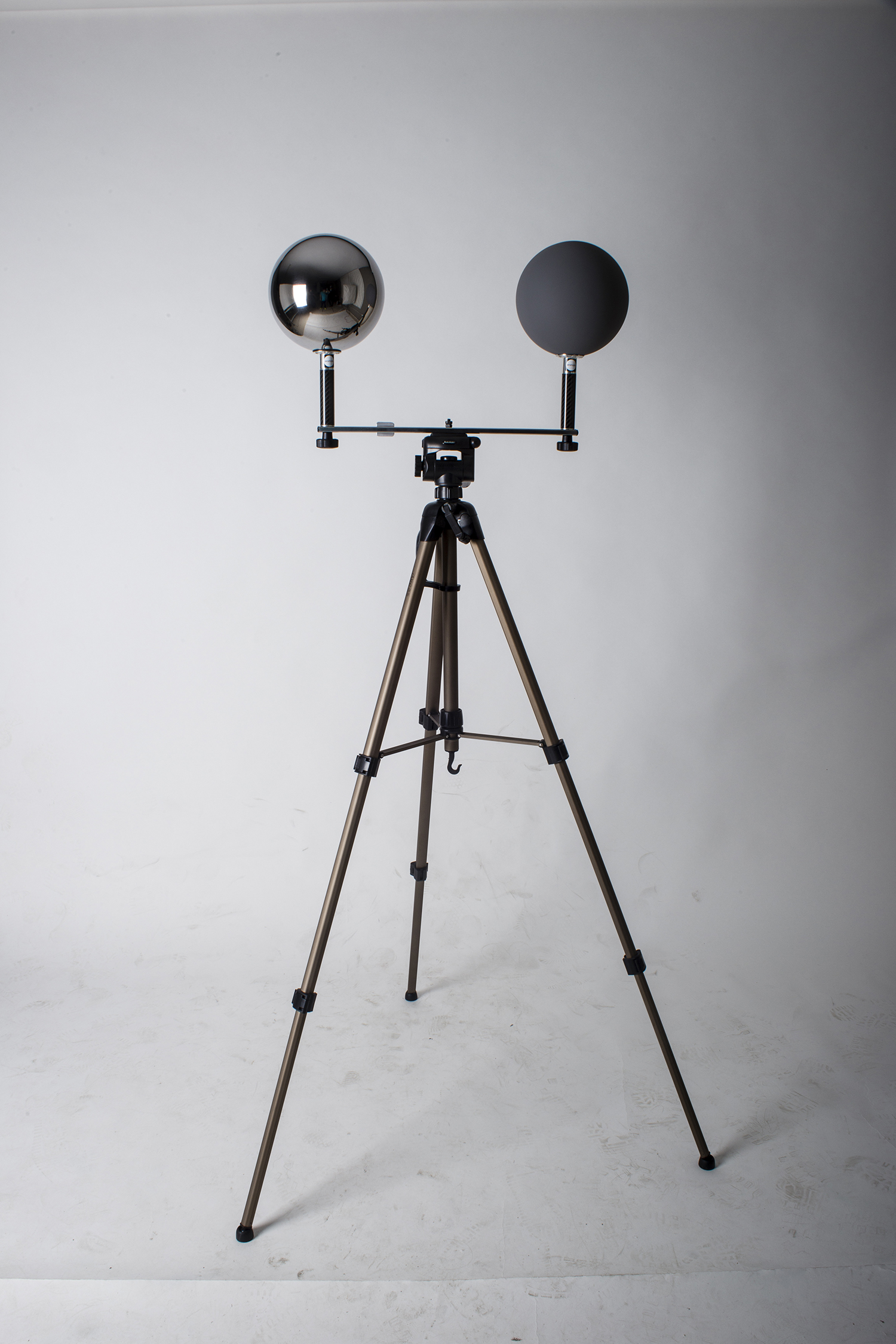
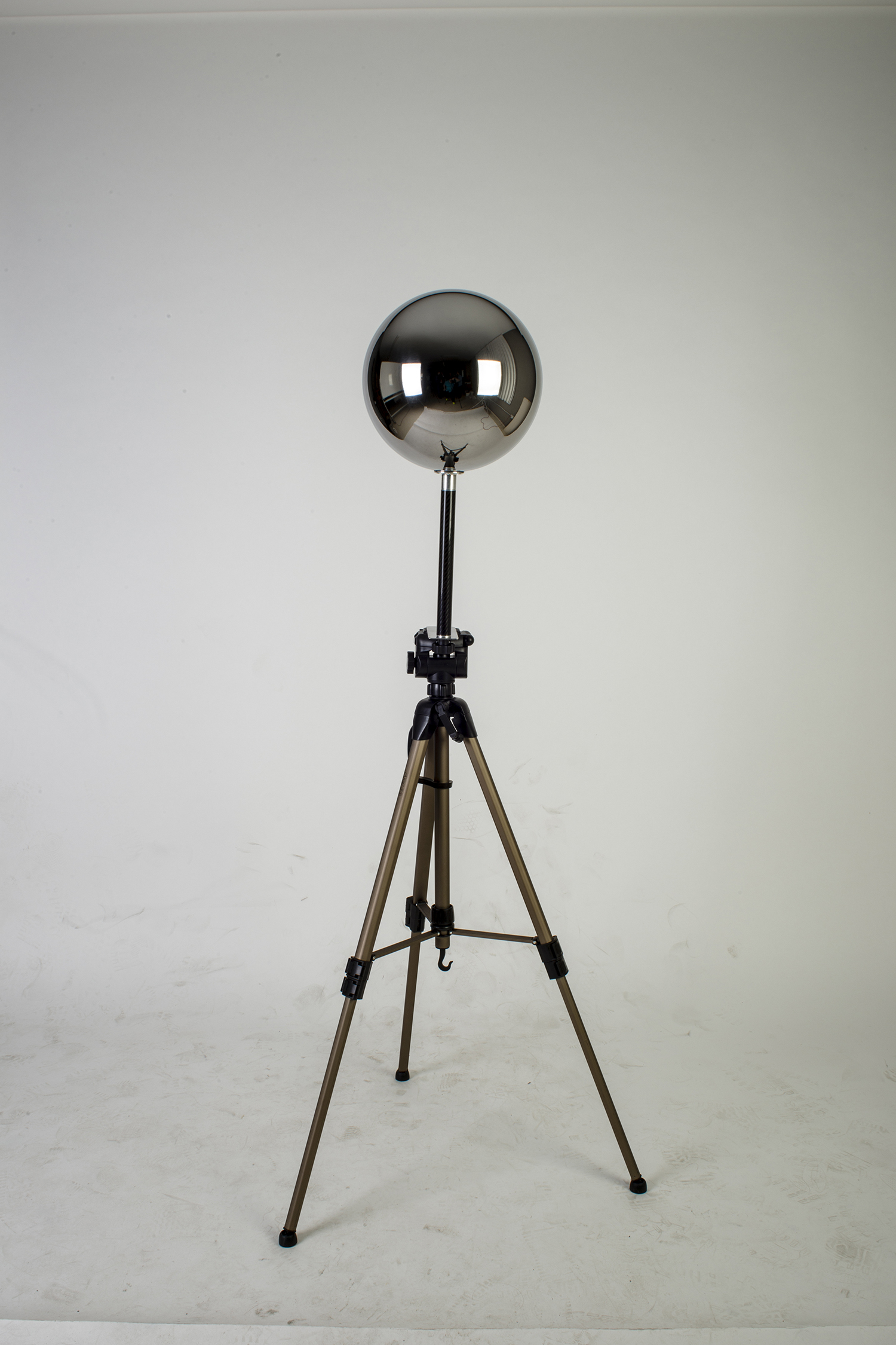
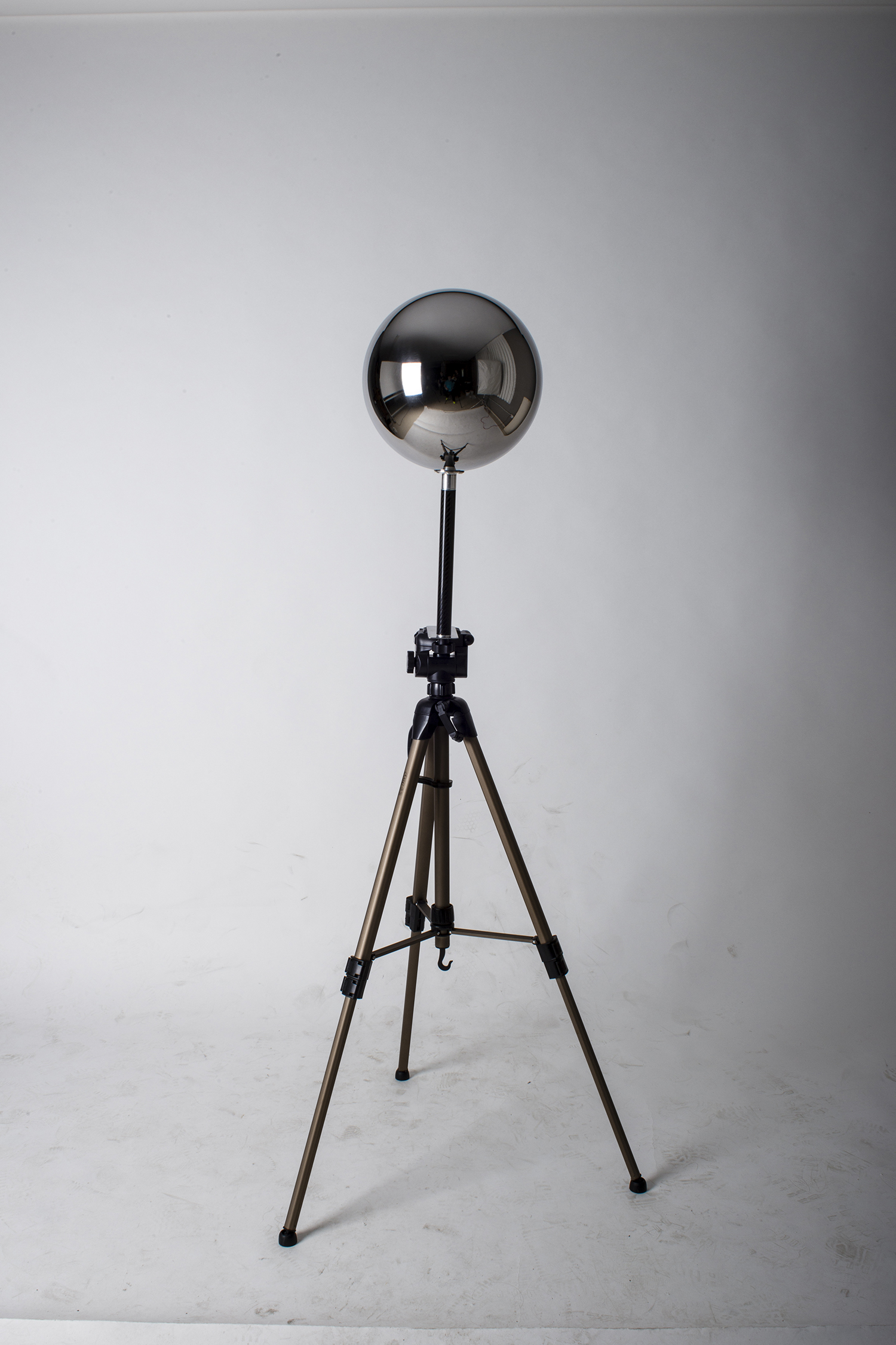
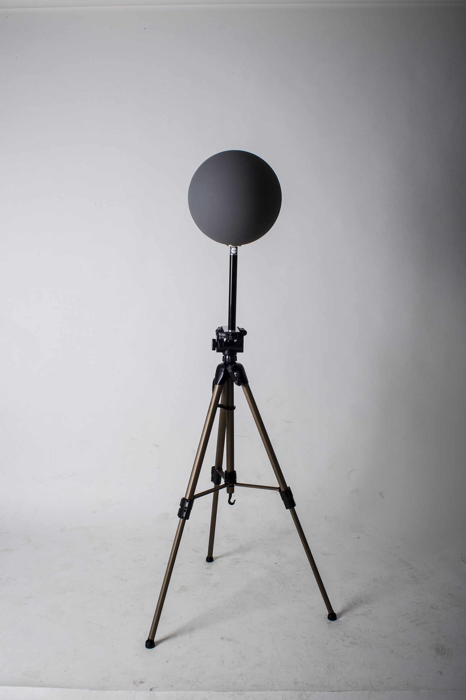
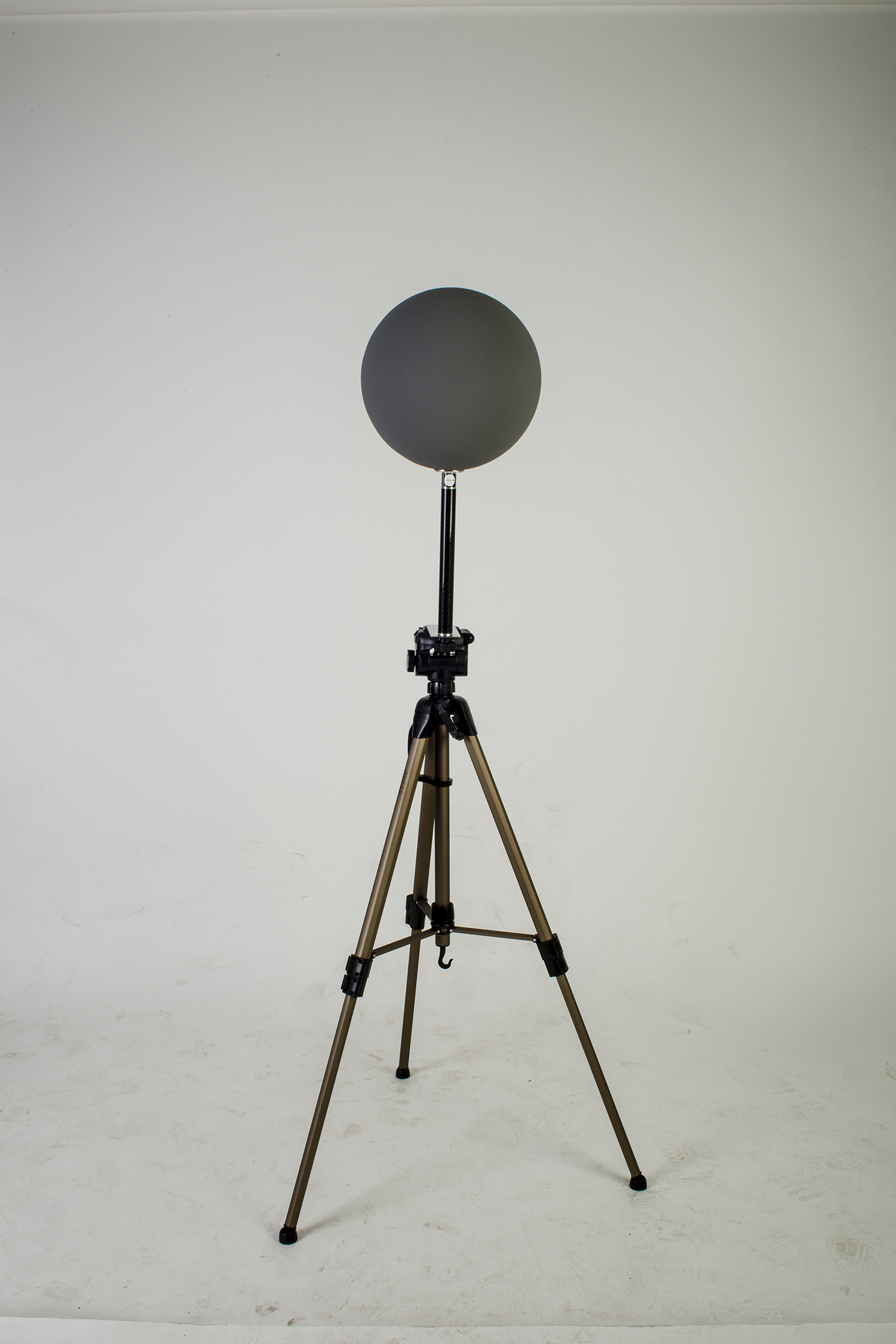
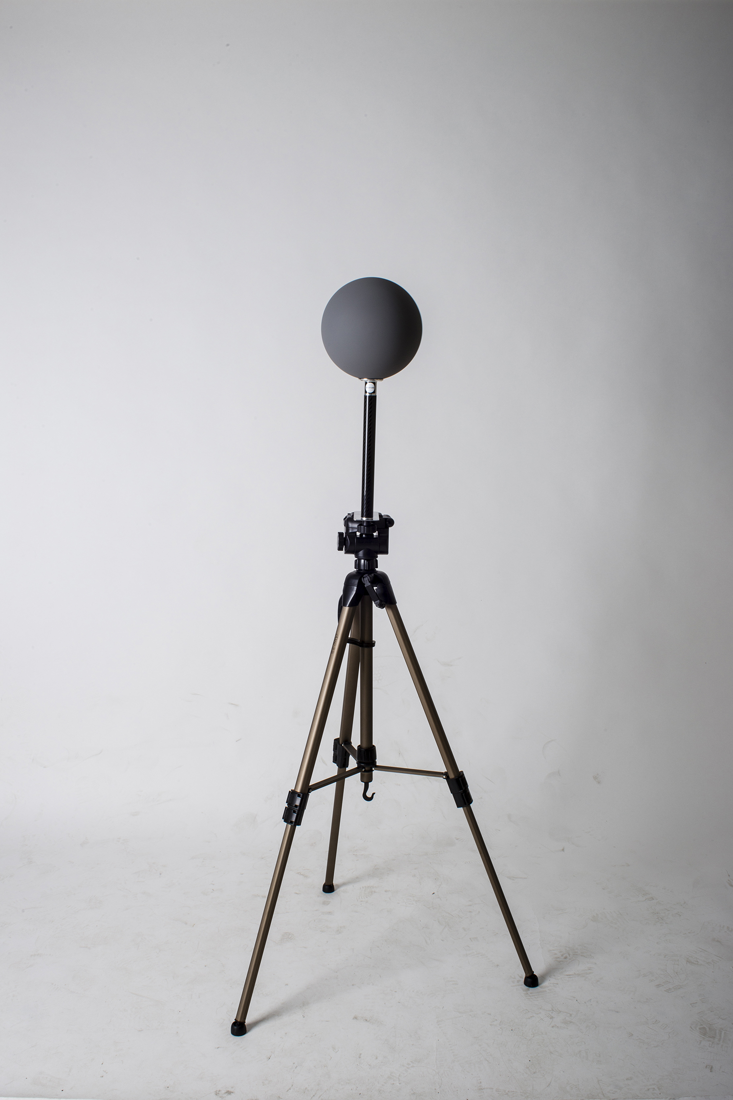
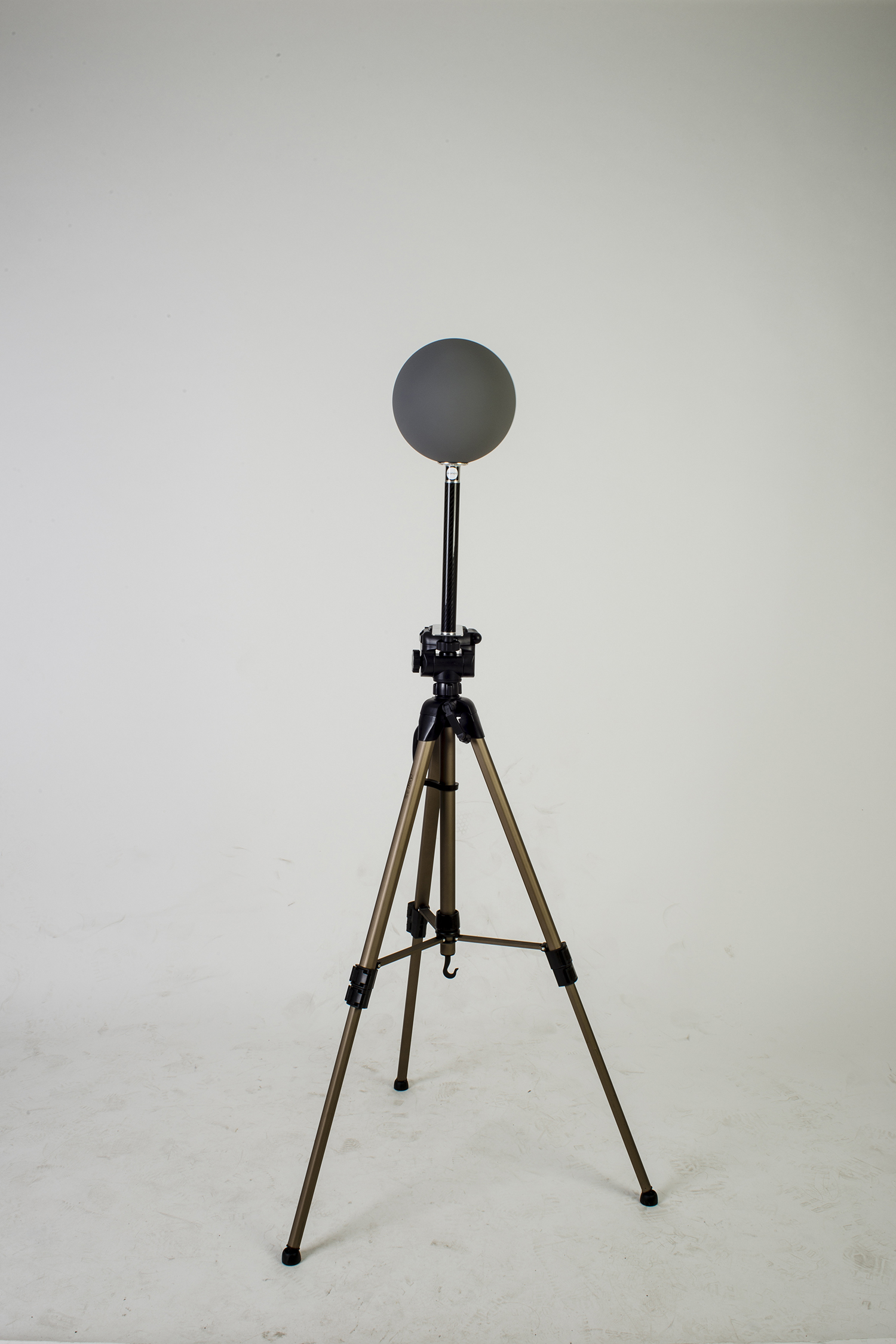
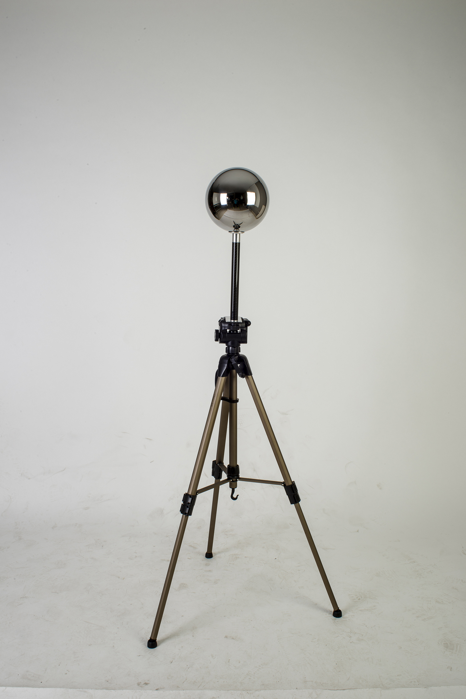
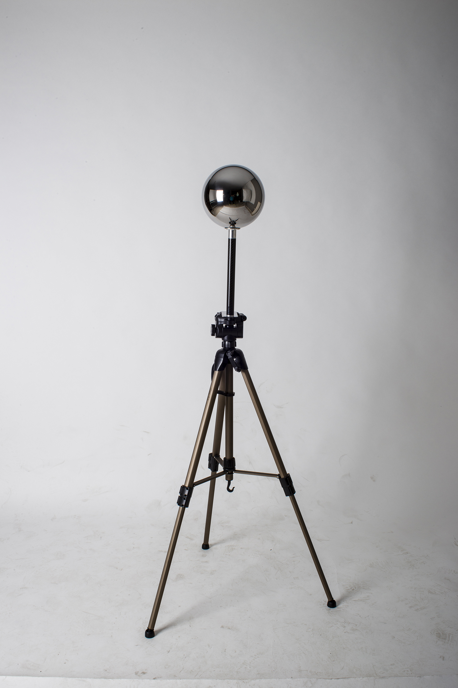
Akromatic base /
As VFX artists we always need to place our color charts and lighting checkers (or practical spheres) somewhere on the ground while shooting bracketed images for panoramic HDRI creation. And we know that every single look-development and / or lighting artist is going to request at least all these references for their tasks back at the facility.
I'm tired of seeing my VFX peers working on set placing their lighting checkers and color charts on top of their backpacks or hard cases to make them visible on their HDRIs. In the best scenario they usually put the lighting checkers on a tripod with it's legs bended.
I've been using my own base to place my lighting checkers and all my workmates keep asking me about it, so it's time to make it available for all of you working on set on a daily basis.
The akromatic base is light, robust and made of high quality stainless steel. It is super simple to attach our lighting checkers to it and keep them safe and more important, visible in all your images. Moving all around the set with your lighting checkers and color charts from take to take is now simple, quick and safe.
The akromatic base is compatible with our lighting checkers "Mono" and "Twins".
New features in UV Layout v2.08.06 /
The new version of UV Layout v2.08.06 was released a few weeks ago and it is time to talk about some of the new exciting features. I'll be mentioning also old tools and features from previous versions that I'm starting to use now and didn't use much before.
- Display -> Light: It changes the way lighting affects the scene, it is very useful when some parts are occluded in the checking window. It has been there for a while but I just started using it not long ago.
- Settings -> F1 F2 F3 F4 F5: This buttons will allow you to create shortcuts for other tools, so instead of using the menus you can map one of the function keys to use that tool.
- Preferences -> Max shells: This option will allow you to increase the number of shells that UV Layout can handle. This is a very very important feature. I use it a lot specially when working with crazy data like 3D scans and photogrammetry.
- Flatten multiple objects at once: It didn't work before but it does now. Just select a bunch of shells and press "r".
- Pack -> Align shells to axes: Select your shells, enable the option "align shells to axes" and click on pack.
- Pack by tiles: Now UDIM organization can be done inside UV Layout. Just need to specify the number of UDIMs in X and Y and click on pack.
- Pack -> Move, scale, rotate: As part of UDIM organization now you can move whole tiles around.
- Trace masks: This is a great feature! Specially useful if you already have a nice UV mapping and suddenly need to add more pieces to the existing UV layout. Just mask out the existing UVs and place the new one in the free space. To do so just place in boxes de new UVs and go to displace -> trace and select your mask. Click on pack and that's it, your new UVs will be placed in the proper space.
Segment marked polys: This is great specially for very quick UV mapping. Just select a few faces click on segment marked polys and UV Layout will create flat projections for them.
- Set size: This is terrific! one of my favourite options. Make the UVs for one object and check the scale under Move/Scale/Rotate -> Set size. Then use that information in the preferences. If later you import a completely different objec, UV Layout will be using the size of the previous object to match the scale between objects. That means all your objects will have exactly same scale and resolution UVs wise. Amazing for texture artists!
- Pin edges: A classic one. When you are relaxing a shell and want to keep the shape, press "pp" on the outer edges to pin them. Then around the eyes or other interior holes press "shift+t" around the edges. Then you can relax the shell keeping the shape of the object.
- Anchor points: Move one point on the corner with "ctrl+MMB" and press "a" to make it anchor point. Then move another point in the opposite corner and do the same. Then press "s" on top of each anchor point. Then "ss" on any point in between the anchors to align them. Combining this with pinned edges will give you perfect shapes.