Hello,
I just published on my Patreon a video about Houdini’s window box.
This video is about how to use the new window box system in Houdini. One of those tools that I've been using for many years at different VFX studios, but now it works out of the box with Houdini and Karma. I hope you find it useful and you can start using it soon in your projects!
All the info on my Patreon site.
texturing
Detailing digi doubles using generic humans /
This is probably the last video of the year, let's see about that.
This time is all about getting your concept sculpts into the pipeline. To do this, we are going to use a generic humanoid, usually provided by your visual effects studio. This generic humanoid would have perfect topology, great uv mapping, some standard skin shaders, isolation maps to control different areas, grooming templates, etc.
This workflow will speed drastically the way you approach digital doubles or any other humanoid character, like this zombie here.
In this video we will focus mainly on wrapping a generic character around any concep sculpt to get a model that can be used for rigging, animation, lookdev, cfx, etc. And once we have that, we will re-project back all the details from the sculpt and we will apply high resolution displacement maps to get all the fine details like skin pores, wrinkles, skin imperfections, etc.
The video is about 2 hours long and we can use this character in the future to do some other videos about character/creature work.
All the info on my Patreon site.
Thanks!
Xuan.
Houdini topo transfer - aka wrap3 /
For a little while I have been using Houdini topo transfer tools instead of Wrap 3. Not saying that I can fully replace Wrap3 but for some common and easy tasks, like wrapping generic humans to scans for both modelling and texturing, I can definitely use Houdini now instead of Wrap 3.
Wrapping generic humans to scans
This technique will allow you to easily wrap a generic human to any actor’s scan to create digital doubles. This workflow can be used during modeling the digital double and also while texturing it. Commonly, a texture artist gets a digital double production model in t-pose or a similar pose that doesn’t necessary match the scan pose. It is a great idea to match both poses to easily transfer color details and surface details between the scan and the production model.
For both situations, modeling or texturing, this is a workflow that usually involves Wrap3 or other proprietary tools for Maya. Now it can also easily be done in Houdini.
First of all, open the ztool provided by the scanning vendor in Zbrush. These photogrammetry scans are usually something around 13 – 18 million of polygons. Too dense for the wrapping process. You can just decimate the model and export it as .obj
In Maya align roughly your generic human and the scan. If the pose is very different, use your generic rig to match (roughly) the pose of the scan. Also make sure both models have the same scale. Scaling issues can be fixed in Wrap3 or Houdini in this case, but I think it is better to fix it beforehand, in a vfx pipeline you will be publishing assets from Maya anyway. Then export both models as .obj
It is important to remove teeth, the interior of the mouth and other problematic parts from your generic human model. This is something you can do in Houdini as well, even after the wrapping, but again, better to do it beforehand.
Import the scan in Houdni.
Create a topo transfer node.
Connect the scan to the target input of the topo transfer.
Bring the base mesh and connect it to the source input of the topo transfer.
I had issues in the past using Maya units (decimeters) so better to scale by 0.1 just in case.
Enable the topo transfer, press enter to activate it. Now you can place landmarks on the base mesh.
Add a couple of landmarks, then ctrl+g to switch to the scan mesh, and align the same landmarks.
Repeat the process all around the body and click on solve.
Your generic human will be wrapped pretty much perfectly to the actor’s scan. Now you can continue with your traditional modeling pipeline, or in case you are using this technique for texturing, move into Zbrush, Mari and or Houdini for transferring textures and displacement maps. There are tutorials about these topics on this site.
Transferring texture data
Import the scan and the wrapped model into Houdini.
Assign a classic shader with the photogrammetry texture connected to its emission color to the scan. Disable the diffuse component.
Create a bakeTexture rop with the following settings.
Resolution = 4096 x 4096.
UV object = wrapped model.
High res object = scan.
Output picture = path_to_file.%(UDIM)d.exr
Format = EXR.
Surface emission color = On.
Baking tab = Tick off Disable lighting/emission and Add baking exports to shader layers.
If you get artifacts in the transferred textures, in the unwrapping tab change the unwrap method to trace closest surface. This is common with lidar, photogrammetry and other dirty geometry.
You can run the baking locally or on the farm.
Take a look at the generated textures.
Mari 4.6 new features and production template /
Hello patrons,
I recorded a new video about the new features in Mari 4.6 released just a few weeks ago. I will also talk about some of the new features in the extension pack 5 and finally I will show you my production template that I've been using lately to do all the texturing and pre-lookDev on many assets for film and tv projects.
This is a big picture of the topics covered in this video. The video will be about 2.5 hours long, and it will be published on my Patreon site.
- Mari 4.6 new features
- New material system explained in depth
- Material ingestion tool
- Optimization settings
- How and where to use geo channels
- New camera projection tools
- Extension pack 5 new features (or my most used tools)
- Production template for texturing and pre-lookDev
All the information on my Patreon feed.
Thanks for your support!
Xuan.
Houdini as scene assembler part 05. User attributes /
Sometimes, specially during the layout/set dressing stage artists have to decide certain rules or patterns to compose a shot. For example let’s say a football stadium. Imagine that the first row of seats is blue, the next row is red and the third row is green.
There are so many ways of doing this, but let’s say that we have thousands of seats and we know the colors that they should have. Then it is easy to make rules and patterns to allow total flexibility later on when texturing and look-deving.
In this example I’m using my favourite tool to explain 3D stuff, Lego figurines. I have 4 rows of Lego heads and I want each of those to have a different Lego face. But at the same time I want to use the same shader for all of them. I just want to have different textures. By doing this I will end up with a very simple and tidy setup, and iteration won’t be a pain.
Doing this in Maya is quite straightforward and I explained the process some time ago in this blog. What I want to illustrate now is another common situation that we face in production. Layout artists and set dresser usually do their work in Maya and then pass it on to look-dev artists and lighting td’s that usually use scene assemblers like Katana, Clarisse, Houdini, or Gaffer.
In this example I want to show you how to handle user attributes from Maya in Houdini to create texture and shader variations.
In Maya select all the shapes and add a custom attribute.
Call it “variation”
Data type integer
Default value 0
Add a different value to each Lego head. Add as many values as texture variations you need to have
Export all the Lego heads as alembic, remember to add the attributes that you want to export to houdini
Import the alembic file in Houdini
Connect all the texture variations to a switch node
This can be done also with shaders following exactly the same workflow
Connect an user data int node to the index input of the switch node and type the name of your attribute
Finally the render comes out as expected without any further tweaks. Just one shader that automatically picks up different textures based on the layout artist criteria
Mixing displacement and multiple bump maps /
A very common situation when look-deving an asset is combining various displacement and bump maps. Having them in different texture maps gives you the possibility to play with them and making very fast changes without going back to Mari and Zbrush and waste a lot of time going back and forward until reaching the right look. You also want to keep busy your look-dev team, of course.
While ago I told you how to combine different displacement maps coming from different sources, today I want to show you how to combine multiple bump maps, with different scales and values. This is a very common situation in vfx, I would say every single asset has at least one displacement layer and one bump layer, but usually, you would have more than one. This is how you can combine multiple bump layers in Maya/Arnold.
- The first thing I'm going to do is add a displacement layer. To make this post easy I'm using a single displacement layer. Refer back to the tutorial I mentioned previously on this post to mix more than one displacement layer.
- Now connect your first bump map layer as usual. Connecting the red channel to the bump input of the shader.
- in the hypershade create a file texture for your second bump layer. In this case a low frequency noise.
- Create an avergage node and two multiply nodes.
- Connect the red channel of the first bump layer to the input 1 of the multiply node. Control the intensity of this layer with the input 2 of the multiply node.
- Repeat with previous step with the second bump layer.
- Connect the outputs of both multiply nodes to the inputs 3D0 and 3D1 of the average node.
- It is extremely important to leave the bump depth at 1 in order to make this work.
Iron Patriot wip 02 /
Another wip of this character. More to come.
Iron Patriot wip 01 /
I'm working on a texturing and look-dev course for elephant vfx and this is the asset that I'm preparing. Just an arm for now but I guess it's time to show you guys something. Stay tuned.
Clarisse shading layers: Crowd in 5 minutes /
One feature that I really like in Clarisse are the shading layers. With them you can drive shaders based on naming convention or location of assets in the scene. With this method you can assign shaders to a very complex scene structure in no time. In this particular case I'll be showing you how to shade an entire army and create shading/texturing variations in just a few minutes.
I'll be using an alembic cache simulation exported from Maya using Golaem. Usually you will get thousand of objects with different naming convention, which makes the shading assignment task a bit laborious. With shading layer rules in Clarisse we can speed up a lot this tedious process
- Import an alembic cache with the crowd simulation through file -> import -> scene
- In this scene I have 1518 different objects.
- I'm going to create an IBL rig with one of my HDRIs to get some decent lighting in the scene.
- I created a new context called geometry where I placed the army and also created a ground plane.
- I also created another context called shaders where I'm going to place all my shaders for the soldiers.
- In the shaders context I created a new material called dummy, just a lambertian grey shader.
- We are going to be using shading layers, to apply shaders globally based on context and naming convention. I created a shading layers called army (new -> shading layer).
- With the pass (image) selected, select the 3D layer and apply the shading layer.
- Using the shading layer editor, add a new rule to apply the dummy shader to everything in the scene.
- I'm going to add a rule for everything called heavyArmor.
- Then just configure the shader for the heavyArmour with metal properties and it's correspondent textures.
- Create a new rule for the helmets and apply the shader that contains the proper textures for the helmets.
- I keep adding rules and shaders for different parts of the sodliers.
- If I want to create random variation, I can create shading layers for specific names of parts or even easier and faster, I can put a few items in a new context and create a new shading rule for them. For the bodies I want to use caucasian and black skin soldiers. I grabbed a few bodies and place them inside a new context called black. Then create a new shading rules where I apply a shader with different skin textures to all the bodies in that context.
- I repeated the same process for the shields and other elements.
- At the end of the process I can have a very populated army with a lot of random texture variations in just a few minutes.
- This is how my shading layers look like at the end of the process.
UDIM workflow in Nuke /
Texture artists, matte painters and environment artists often have to deal with UDIMs in Nuke. This is a very basic template that hopefully can illustrate how we usually handle this situation.
Cons
- Slower than using Mari. Each UDIM is treated individually.
- No virtual texturing, slower workflow. Yes, you can use Nuke's proxies but they are not as good as virtual texturing.
Pros
- No paint buffer dependant. Always the best resolution available.
- Non destructive workflow, nodes!
- Save around £1,233 on Mari's license.
Workflow
- I'll be using this simple footage as base for my matte.
- We need to project this in Nuke and bake it on to different UDIMs to use it later in a 3D package.
- As geometry support I'm using this plane with 5 UDIMs.
- In Nuke, import the geometry support and the footage.
- Create a camera.
- Connect the camera and footage using a Project 3D node.
- Disable the crop option of the Project 3D node. If not the proejctions wouldn't go any further than UV range 0-1.
- Use a UV Tile node to point to the UDIM that you need to work on.
- Connect the img input of the UV Tile node to the geometry support.
- Use a UV Project node to connect the camera and the geometry support.
- Set projection to off.
- Import the camera of the shot.
- Look through the camera in the 3D view and the matte should be projected on to the geometry support.
- Connect a Scanline Render to the UV Project.
- Set the projection model to UV.
- In the 2D view you should see the UDIM projection that we set previously.
- If you need to work with a different UDIM just change the UV Tile.
- So this is the basic setup. Do whatever you need in between like projections, painting and so on to finish your matte.
- Then export all your UDIMs individually as texture maps to be used in the 3D software.
- Here I just rendered the UDIMs extracted from Nuke in Maya/Arnold.
Hulkbuster /
I've been working on this character for a texturing and look-dev course that I'll be presenting pretty soon. Hope you like it.
Import UDIMs in Zbrush /
One of the most common tasks once your colour textures are painted is going to Zbrush or Mudbox to sculpt some heavy details based on what you have painted in your colour textures.
We all use UDIMs of course, but importing UDIMs in Zbrush is not that easy. Let's see how this works.
- Export all your colour UDIMs out of Mari.
- Import your 3D asset in Zbrush and go to Polygroups -> UV Groups. This will create a polygroups based on UDIMs.
- With ctrl+shift you can isolate UDIMs.
- Now you have to import the texture that corresponds to the isolated UDIM.
- Go to Texture -> Import. Do not forget to flip it vertically.
- Go to Texture Map and activate the texture.
- At this point you are only viewing the texture, not applying it.
- Go to Polypaint, enable Colorize and click on Polypaint from texture.
- This will apply the texture to the mesh. As it's based on polypaint, the resolution of the texture will be based on the resolution of the mesh. If it doesn't look right, just go and subdivide the mesh.
- Repeat the same process for all the UDIMs and you'll be ready to start sculpting.
Export from Maya to Mari /
Yes, I know that Mari 3.x supports OpenSubdiv, but I've had some bad experiences already where Mari creates artefacts on the meshes.
So for now, I will be using the traditional way of exporting subdivided meshes from Maya to Mari. These are the settings that I usually use to avoid distortions, stretching and other common issues.
Combining Zbrush and Mari displacements in Clarisse /
We all have to work with displacement maps painted in both Zbrush and Mari.
Sometimes we use 32 bits floating point maps, sometimes 16 bits maps, etc. Combining different displacement depths and scales is a common task for a look-dev artist working in the film industry.
Let's see how to setup different displacement maps exported from Zbrush and Mari in Isotropix Clarisse.
- First of all, have a look at all the individual displacement maps to be used.
- The first one has been sculpted in Zbrush and exported as .exr 32 bits displacement map. The non-displacement value is zero.
- The second one has been painted in Mari and exported also as .exr 32 bits displacement map. Technically this map is exactly the same as the Zbrush one, the only difference here is the scale.
- The third displacement map in this exercise also comes from Mari, but in this case it's a .tif 16 bits displacement map, which means that the mid-point will be 0,5 instead of zero.
- We need to combine all of them in Clarisse and get the expected result.
- Start creating a displacement node and assigning it to the mesh.
- We consider the Zbrush displacement as our main displacement layer. That said, the displacement node has to be setup like the image below. The offset or non-displacement value has to be zero, and the front value 1. This will give us exactly the same look that we have in Zbrush.
- In the material editor I'm connecting a multiply node after every single displacement layer. The input 2 is 1.1.1 by default. Increasing or reducing this value will control the strength of each displacement layer. It is not necessary to control the intensity of the Zbrush layer unless you want to do it. But it is necessary to reduce the intensity of the Mari displacement layers as they are way off compared with the Zbrush intensity.
- I also added an add node right after the 16 bits Mari displacement subtracting the value -0.5 in order to remap the value at the same level than the other 32 bits maps with non-displacement value of zero.
- Finally I used add nodes to mix all the displacement layers.
- It is a good idea to setup all the layers individually to find the right look.
- No displacement at all.
- Zbrush displacement.
- Mari high frequency detail.
- Mari low frequency detail.
- All displacement layers combined.
Environment reconstruction + HDR projections /
I've been working on the reconstruction of this fancy environment in Hackney Wick, East London.
The idea behind this exercise was recreating the environment in terms of shape and volume, and then project HDRIs on the geometry. Doing this we can get more accurate lighting contribution, occlusion, reflections and color bleeding. Much better environment interaction between 3D assets. Which basically means better integrations for our VFX shots.
I tried to make it as simple as possible, spending just a couple of hours on location.
- The first thing I did was drawing some diagrams of the environment and using a laser measurer cover the whole place writing down all the information needed for later when working on the virtual reconstruction.
- Then I did a quick map of the environment in Photoshop with all the relevant information. Just to keep all my annotations clean and tidy.
- With drawings and annotations would have been good enough for this environment, just because it's quite simple. But in order to make it better I decided to scan the whole place. Lidar scanning is probably the best solution for this, but I decided to do it using photogrammetry. I know it takes more time but you will get textures at the same time. Not only texture placeholders, but true HDR textures that I can use later for projections.
- I took around 500 images of the whole environment and ended up with a very dense point cloud. Just perfect for geometry reconstruction.
- For the photogrammetry process I took around 500 shots. Every single one composed of 3 bracketed exposures, 3 stops apart. This will give me a good dynamic range for this particular environment.
- Combined the 3 brackets to create rectilinear HDR images. Then exported them as both HDR and LDR. The exr HDRs will be used for texturing and the jpg LDR for photogrammetry purpose.
- Also did a few equirectangular HDRIs with even higher dynamic ranger. Then I projected these in Mari using the environment projection feature. Once I completed the projections from different tripod positions, cover the remaining areas with the rectilinear HDRs.
- These are the five different HDRI positions and some render tests.
- The next step is to create a proxy version of the environment. Having the 3D scan this so simple to do, and the final geometry will be very accurate because it's based on photos of the real environment. You could also do a very high detail model but in this case the proxy version was good enough for what I needed.
- Then, high resolution UV mapping is required to get good texture resolution. Every single one of my photos is 6000x4000 pixels. The idea is to project some of them (we don't need all of them) through the photogrammetry cameras. This means great texture resolution if the UVs are good. We could even create full 3D shots and the resolution would hold up.
- After that, I imported in Mari a few cameras exported from Photoscan and the correspondent rectilinear HDR images. Applied same lens distortion to them and project them in Mari and/or Nuke through the cameras. Always keeping the dynamic range.
- Finally exported all the UDIMs to Maya (around 70). All of them 16 bit images with the original dynamic range required for 3D lighting.
- After mipmapped them I did some render tests in Arnold and everything worked as expected. I can play with the exposure and get great lighting information from the walls, floor and ceiling. Did a few render tests with this old character.
Bake from Nuke to UVs /
- Export your scene from Maya with the geometry and camera animation.
- Import the geometry and camera in Nuke.
- Import the footage that you want to project and connect it to a Project 3D node.
- Connect the cam input of the Project 3D node to the previously imported camera.
- Connect the img input of the ReadGeo node to the Project 3D node.
- Look through the camera and you will see the image projected on to the geometry through the camera.
- Paint or tweak whatever you need.
- Use a UVProject node and connect the axis/cam input to the camera and the secondary input to the ReadGeo.
- Projection option of the UVProjection should be set as off.
- Use a ScanlineRender node and connect it’s obj/scene input to the UVProject.
- Set the projection mode to UV.
- If you swap from the 3D view to the 2D view you will see your paint work projected on to the geometry uvs.
- Finally use a write node to output your DMP work.
- Render in Maya as expected.
Robot shot 01 /
This is a work in progress image.
More shots on their way.
Combining Zbrush and Mari displacement maps /
Short and sweet (hopefully).
It seems to be quite a normal topic these days. Mari and Zbrush are commonly used by texture artists. Combining displacement maps in look-dev is a must.
I'll be using Maya and Arnold for this demo but any 3D software and renderer is welcome to use the same workflow.
- Using Zbrush displacements is no brainer. Just export them as 32 bit .exr and that's it. Set your render subdivisions in Arnold and leave the default settings for displacement. Zero value is always 0 and height should be 1 to match your Zbrush sculpt.
- These are the maps that I'm using. First the Zbrush map and below the Mari map.
- No displacement at all in this render. This is just the base geometry.
- In this render I'm only using the Zbrush displacement.
- In order to combine Zbrush displacement maps and Mari displacement maps you need to normalise the ranges. If you use the same range your Mari displacement would be huge compared with the Zbrush one.
- Using a multiply node is so easy to control the strength of the Mari displacement. Connect the map to the input1 and play with the values in the input2.
- To mix both displacement maps you can use an average node. Connect the Zbrush map to the input0 and the Mari map (multiply node) to the input1.
- The average node can't be connected straight o the displacement node. Use ramp node with the average node connected to it's color and then connect the ramp to the displacement default input.
- In this render I'm combining both, Zbrush map and Mari map.
- In this other example I'm about to combine two displacements using a mask. I'll be using a Zbrush displacement as general displacement, and then I'm going to use a mask painted in Mari to reveal another displacement painted in Mari as well.
- As mask I'm going to use the same symbol that I used before as displacement 2.
- And as new displacement I'm going to use a procedural map painted in Mari.
- The first thing to do is exactly the same operation that we did before. Control the strength of the Mari's displacement using a multiply node.
- Then use another multiply node with the Mari's map (multiply) connected to it's input1 and the mask connected to it's input2. This will reveal the Mari's displacement only in the white areas of the mask.
- And the rest is exactly the same as we did before. Connect the Zbrush displacement to the input0 of the average node and the Mari's displacement (multiply) to the input1 of the average node. Then the average node to the ramp's color and the ramp to the displacement default input.
- This is the final render.
Clarisse UV interpolation /
When subdividing models in Clarisse for rendering displacement maps, the software subdivides both geometry and UVs. Sometimes we might need to subdivide only the mesh but keeping the UVs as they are originally.
This depends on production requirements and obviously on how the displacement maps were extracted from Zbrush or any other sculpting package.
If you don't need to subdivide the UVs first of all you should extract the displacement map with the option SmoothUV turned off.
Then in Clarisse, select the option UV Interpolation Linear.
By default Clarisse sets the UVs to Smooth.
You can easily change it to Linear.
Render with smooth UVs.
Render with linear UVs.
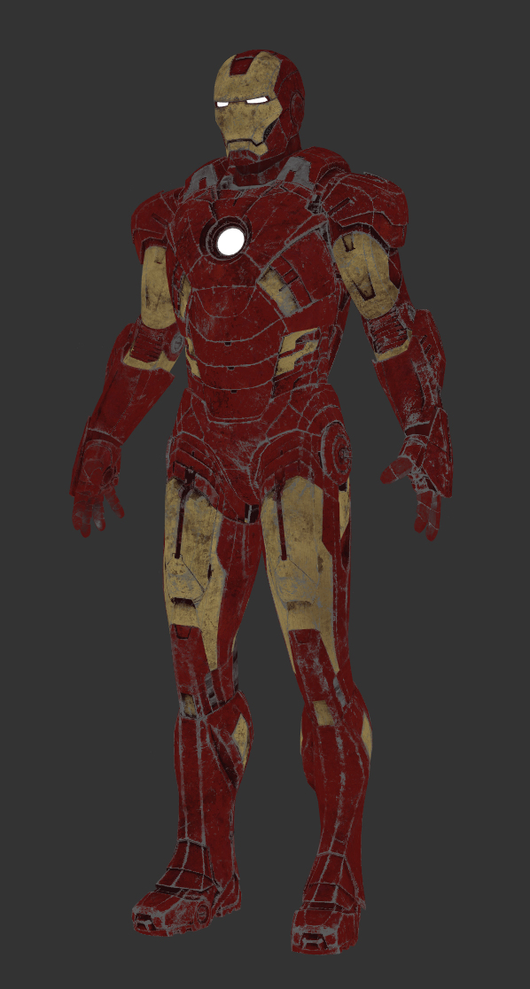
Iron Man Mark 7 /
Speed texturing & look-deving session for this fella.
It will be used for testing my IBLs and light-rigs.
Renders with different lighting conditions and backplates on their way.
These are the texture channels that I painted for this suit. Tried to keep everything simple. Only 6 texture channels, 3 shaders and 10 UDIMs.
Color
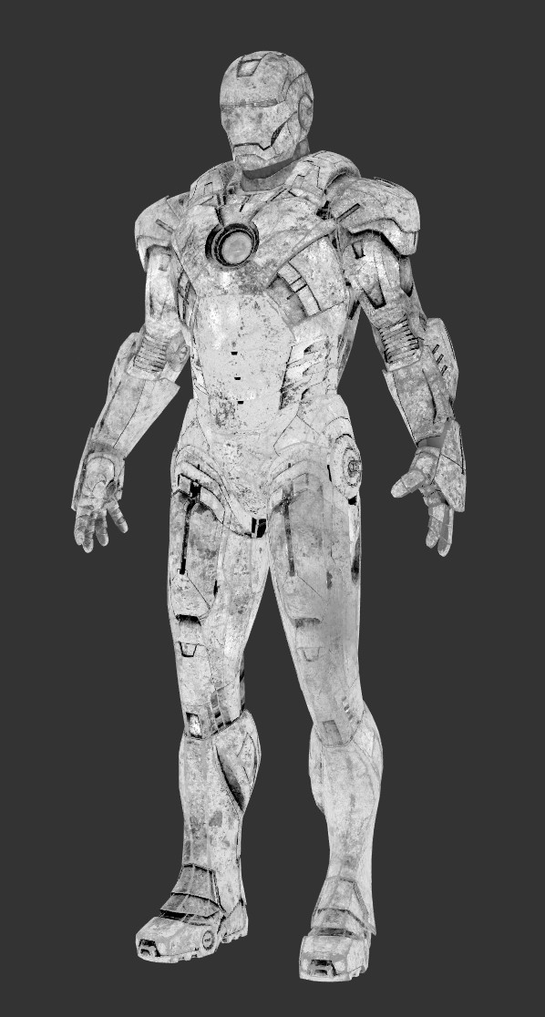
Specular
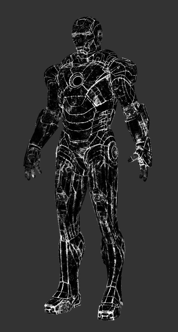
Mask 1
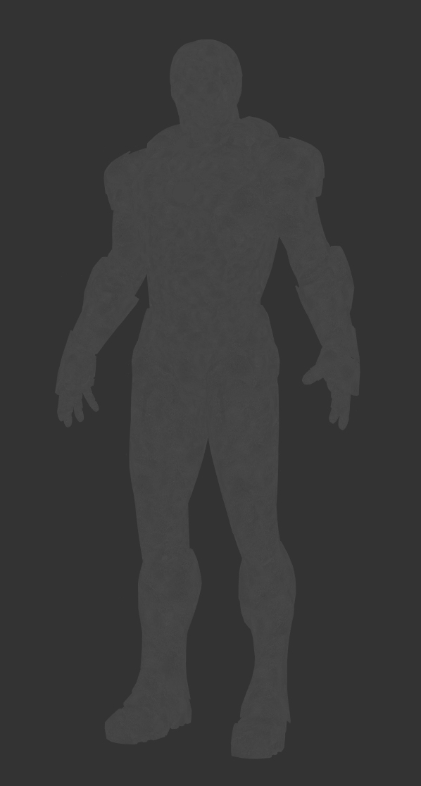
Color 2

Roughness

Fine displacement